Axial compression electrical connector for annular corrugated coaxial cable

a technology of annular corrugated coaxial cable and axial compression, which is applied in the direction of coupling device connection, two-part coupling device, electrical apparatus, etc., can solve the problems of significant increase in body diameter and overall weight, and extensive machining steps of the connector during manufactur

Inactive Publication Date: 2007-10-02
ANDREW LLC
View PDF16 Cites 48 Cited by
  • Summary
  • Abstract
  • Description
  • Claims
  • Application Information

AI Technical Summary

Benefits of technology

[0020]A connector 1 comprises a coupling nut 3 surrounding an interface 5 which mates to a body 7. To reduce metal materials requirements and decrease the overall weight of the connector 1, the body 7 may be formed with a body inner portion 9 and a body overmolding 11. Similarly, the coupling nut 3 may be formed with a coupling nut inner portion 13 and a coupling nut overmolding 14. The body and coupling nut overmolding(s) 11, 14 may be a polymeric material such as polycarbonate or other plastic injection molded about the corresponding inner portion. A textured surface treatment 16 may be applied to the metal inner body and coupling nut portions 9, 13 to improve adhesion with the overmolding.
[0021]As shown in FIG. 3, a connector 1 according to the invention is ready for installation upon a cable 15 without any assembly / disassembly requirements. The body inner portion 9 and interface 5 are coupled together in an interference fit along the connector end 17 bore of the body inner portion 9 and a corresponding cable end 19 outer diameter of the interface 5. Within the connector 1 a flare ring 21 is retained by an initial interference fit within the body 7 and adjacent to a cable end 19 of the interface 5. The flare ring 21 has a beveled flare seat 23 and a retaining lip 25 that form an outer conductor groove 27 open to the cable end 19 of the connector 1. Alternatively, the beveled flare seat 23 and retaining lip 25 that form the outer conductor groove 27 may be formed in the cable end of the interface 5, eliminating the flare ring 21.
[0022]A spring finger ring 29, for example as shown in FIGS. 4 and 5, is located within the body 7 bore coupled to the cable end 19 of the body inner portion 9. The spring finger ring 29 has a plurality of spring finger(s) 31 extending towards the connector end 17. Each of the spring finger(s) 31 has an inward projecting bead 33 at the tip. The body overmolding 11 at the cable end 19 may be formed extending inward to an inner radius of the spring finger ring 29 assisting with the retention of the spring finger ring 29 within the body inner portion 9 bore. Also, an angled face formed in the body overmolding 11 at the cable end 19 may provide a guide surface 35 for the insertion of the cable 15 into the connector 1.
[0030]The invention provides an environmentally sealed connector 1 with improved installation characteristics. Depending upon the material characteristics and dimensions of the particular cable 15 used, the connector 1 may be quickly and securely attached using a compact hand tool. Because threading between the body 7 and interface 5 has been eliminated by configuration for mounting via axial compression, the body 7 and interface 5 do not need to be sized to support exterior wrench flats and or threads between the interface 5 and the body 7. Therefore, even with larger diameter cable(s) 15, the largest body 7 diameter may be easily configured to be less than the largest coupling nut 3 diameter which enables the installation of connectors and cables according to the invention in small spaces and or alongside each other in closer proximity. Because the factory pre-assembled connector 1 does not require any disassembly or other preparation before mounting upon a cable, the opportunity for losing or damaging an essential part of the connector 1 has been eliminated. In addition to reduced wall thickness requirements, through the application of overmolded polymeric outer surfaces and body 7 extensions, the connector 1 has significantly reduced weight.
[0031]The invention also provides significant manufacturing and materials cost efficiencies. The application of polymeric overmolding for outer surfaces significantly reduces the metal content of the connector 1 while the inner portions of the body 7 and coupling nut 3 maintain a fully contiguous metallic electrical enclosure with suitable levels of strength. Because the invention applies axial compression to attach the connector 1 to a cable, threading is eliminated with respect to the clamping of the outer conductor. This allows the spring finger ring 29 to be permanently mounted within the body 7 without rotatability, greatly reducing the number of threading, shoulder, step and or groove machining steps required during manufacture. Further, the greatly simplified surfaces of the body 7, interface 5 and or spring finger ring 29 according to the invention creates an opportunity for connector 1 component manufacture using cost effective metal injection molding technologies.TABLE OF PARTS

Problems solved by technology

To allow the spring finger ring to be rotationally disassociated from the body, a series of retaining grooves, steps and or shoulders have previously been applied, resulting in a connector requiring extensive machining steps during manufacture and having a significantly increased body diameter and overall weight.

Method used


Image

  • Axial compression electrical connector for annular corrugated coaxial cable
  • Axial compression electrical connector for annular corrugated coaxial cable
  • Axial compression electrical connector for annular corrugated coaxial cable

Examples


Embodiment Construction

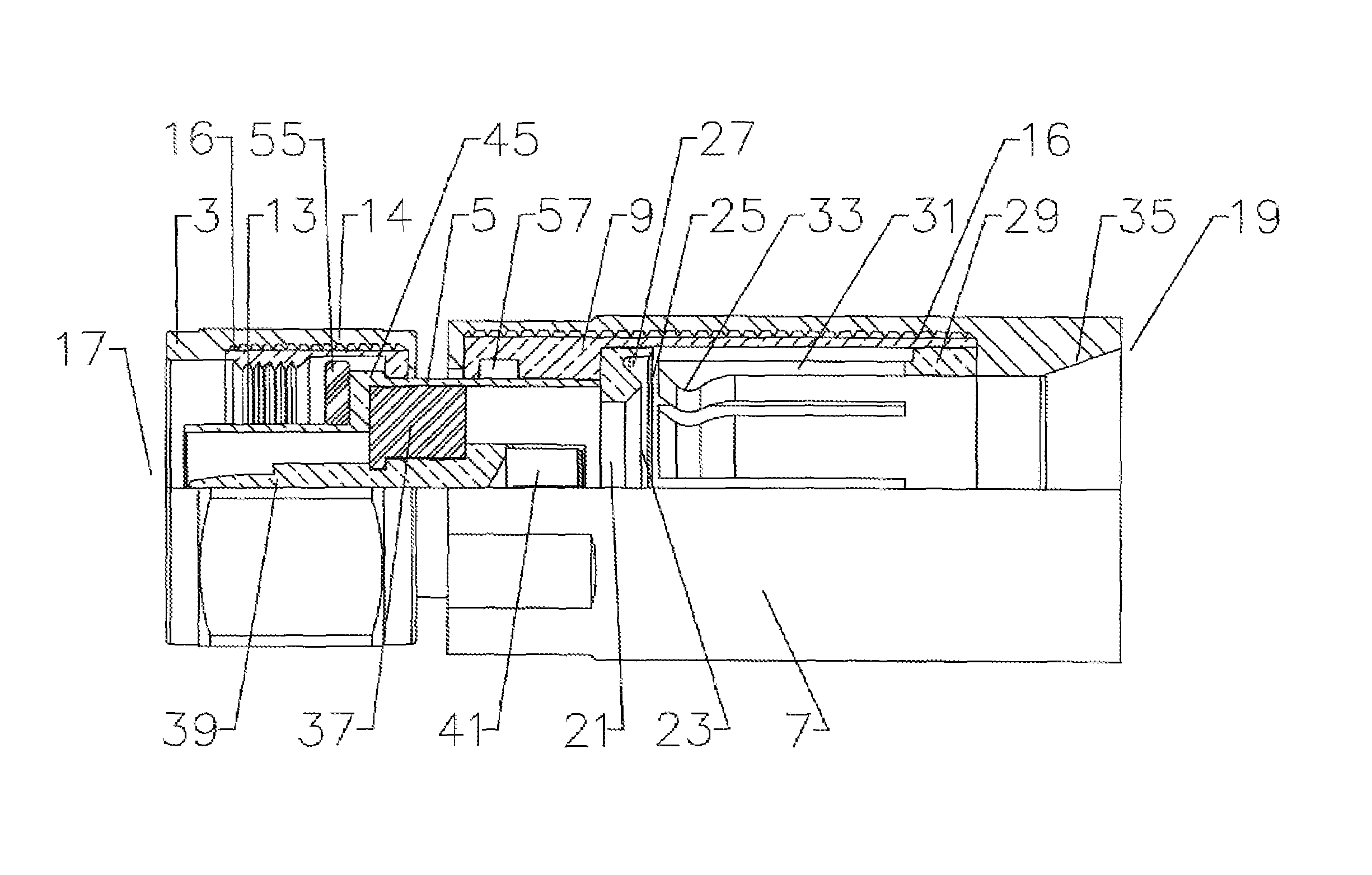
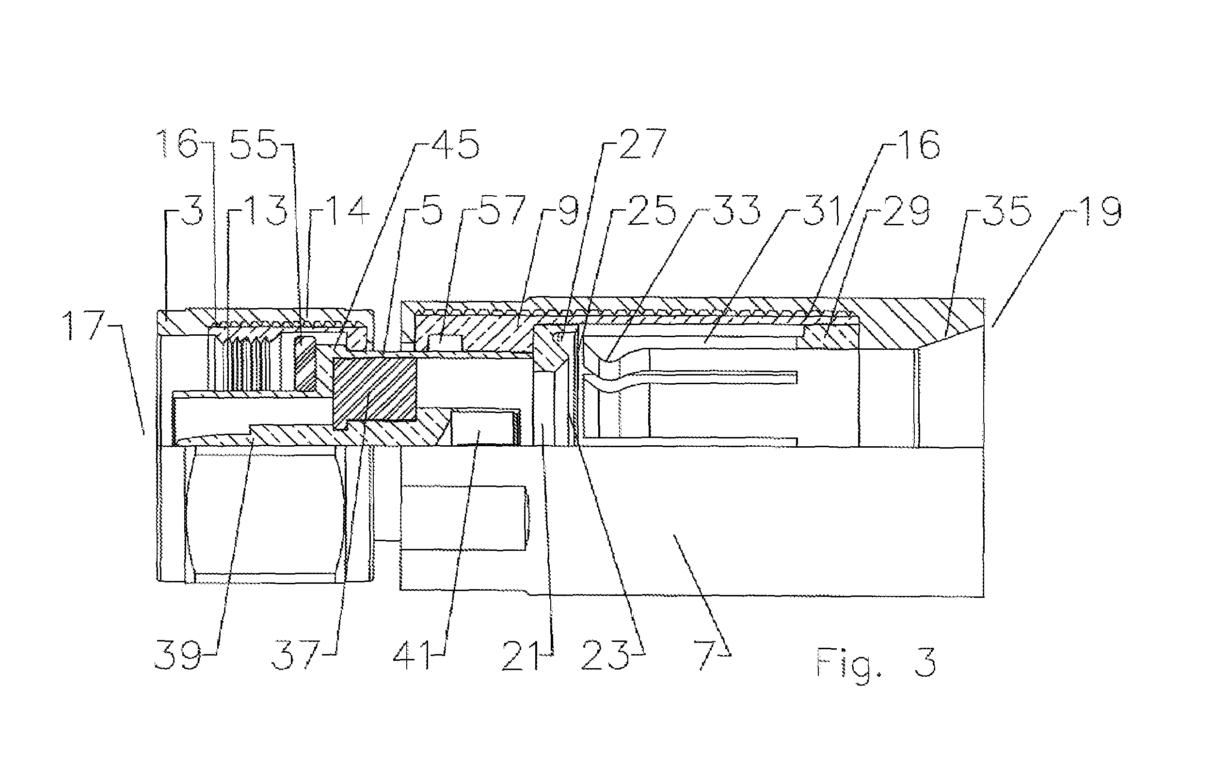
[0017]The inventor(s) have recognized that the prior threaded spring finger connectors require extensive machining operations upon the body, interface and thrust washer or spring finger ring during manufacture to generate the interconnection threads and or multiple guide grooves / steps and or shoulders which rotatably retain the thrust washer or spring finger ring within the body.

[0018]Also, the inventors have recognized that prior connectors have typically been machined from solid metal bar stock resulting in significant materials costs. Expanded connector body dimensions required to provide suitable tightening tooling surfaces, strength for threaded interconnect surfaces as well as to rotatably enclose the thrust washer, spring finger ring or the like further increases the materials requirements and installation difficulties.

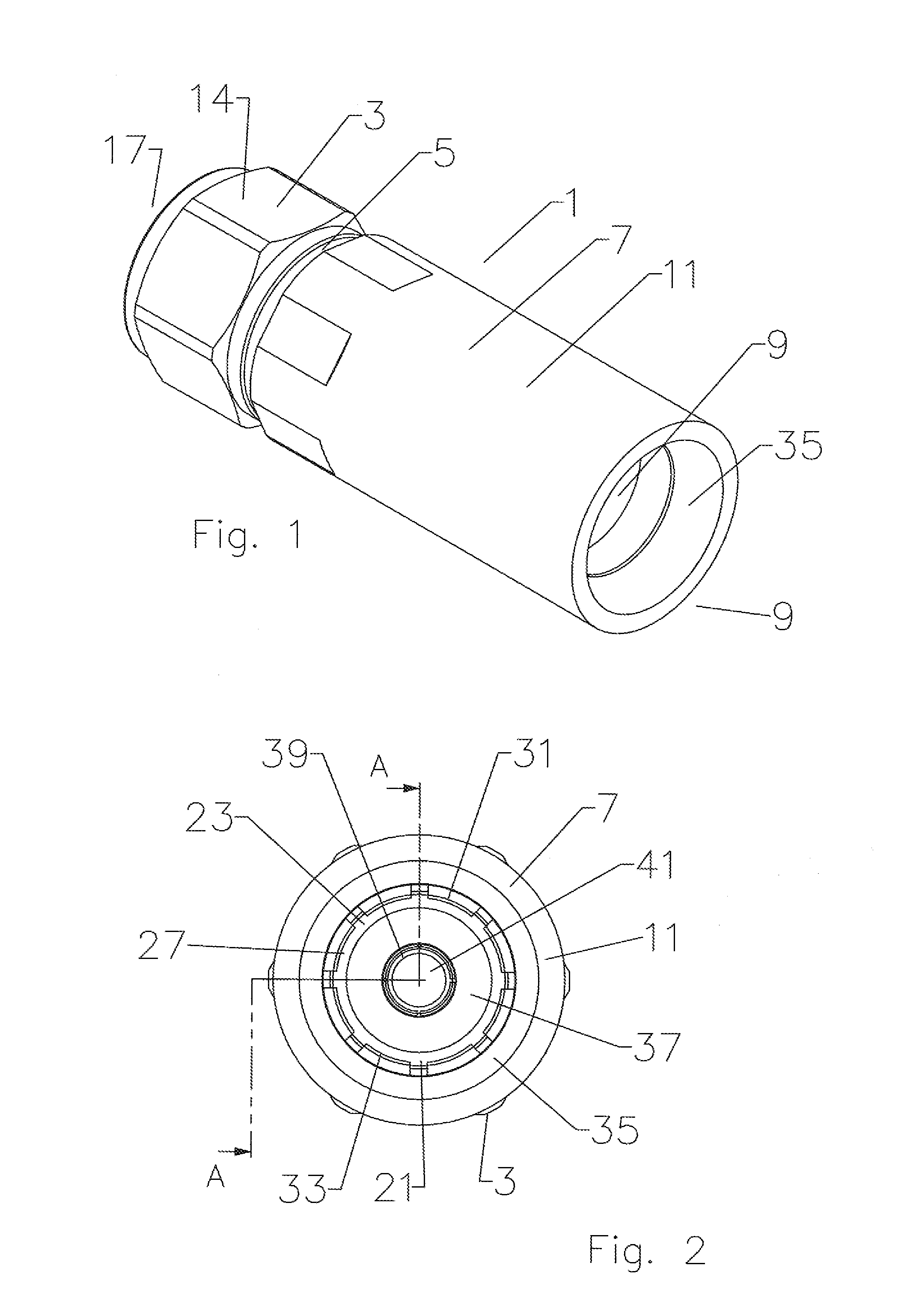
[0019]The invention will be described in detail with respect to FIGS. 1-7 in a standard Type-N connector interface for use with annular corrugated solid outer ...


PUM


Abstract

An electrical connector having a longitudinal axis with interface and cable ends for coaxial cable having an annular corrugated solid outer conductor. The connector having a body and an interface joined in an interference fit along the longitudinal axis of the connector. A spring finger ring within a bore of the body is rigidly connected to the body. The spring finger ring having a plurality of spring fingers extending towards an connector end; the spring fingers having an inward projecting bead at the connector end. The spring fingers positioned opposite an outer conductor groove open to the cable end, the outer conductor groove proximate the cable end of the interface.

Description

BACKGROUND OF INVENTION[0001]1. Field of the Invention[0002]The invention relates to an electrical connector. More particularly the invention relates to an electrical connector installable upon an electrical cable having an annular corrugated outer conductor by application of axial compression without disassembly of the connector.[0003]2. Description of Related Art[0004]Connectors for corrugated outer conductor cable are used throughout the semi-flexible corrugated coaxial cable industry.[0005]Previously, connectors have been designed to attach to annular corrugation outer conductor coaxial cable using mechanical compression via threaded connections between a body and an interface operable to clamp a leading edge of the outer conductor. Typically, the clamping is made against a clamping surface of the interface that is beveled to match the angle of a flared leading edge of the outer conductor. Clamping the leading edge of the outer conductor against the clamping surface is a thrust ...

Claims


Application Information

Patent Timeline
Patent Type & Authority Patents(United States)
IPC IPC(8): H01R9/05H01R24/38
CPCH01R9/0527H01R24/564H01R2103/00H01R9/05
Inventor WLOS, JAMES J.DYKSTRA, JOHNLEE, JOONPAYNTER, JEFFREY
Owner ANDREW LLC
Why Eureka
Try Eureka