Wheel drive system for independently driving right and left wheels of vehicle
a technology of independent driving and right and left wheels, which is applied in the direction of battery/fuel cell control arrangement, electric devices, electric devices, etc., can solve the problems of system requiring a large necessary space to degrade in compactness and quietness, and achieve the effect of improving compactness, high vehicle installation ability, and suppressing gear nois
- Summary
- Abstract
- Description
- Claims
- Application Information
AI Technical Summary
Benefits of technology
Problems solved by technology
Method used
Image
Examples
first embodiment
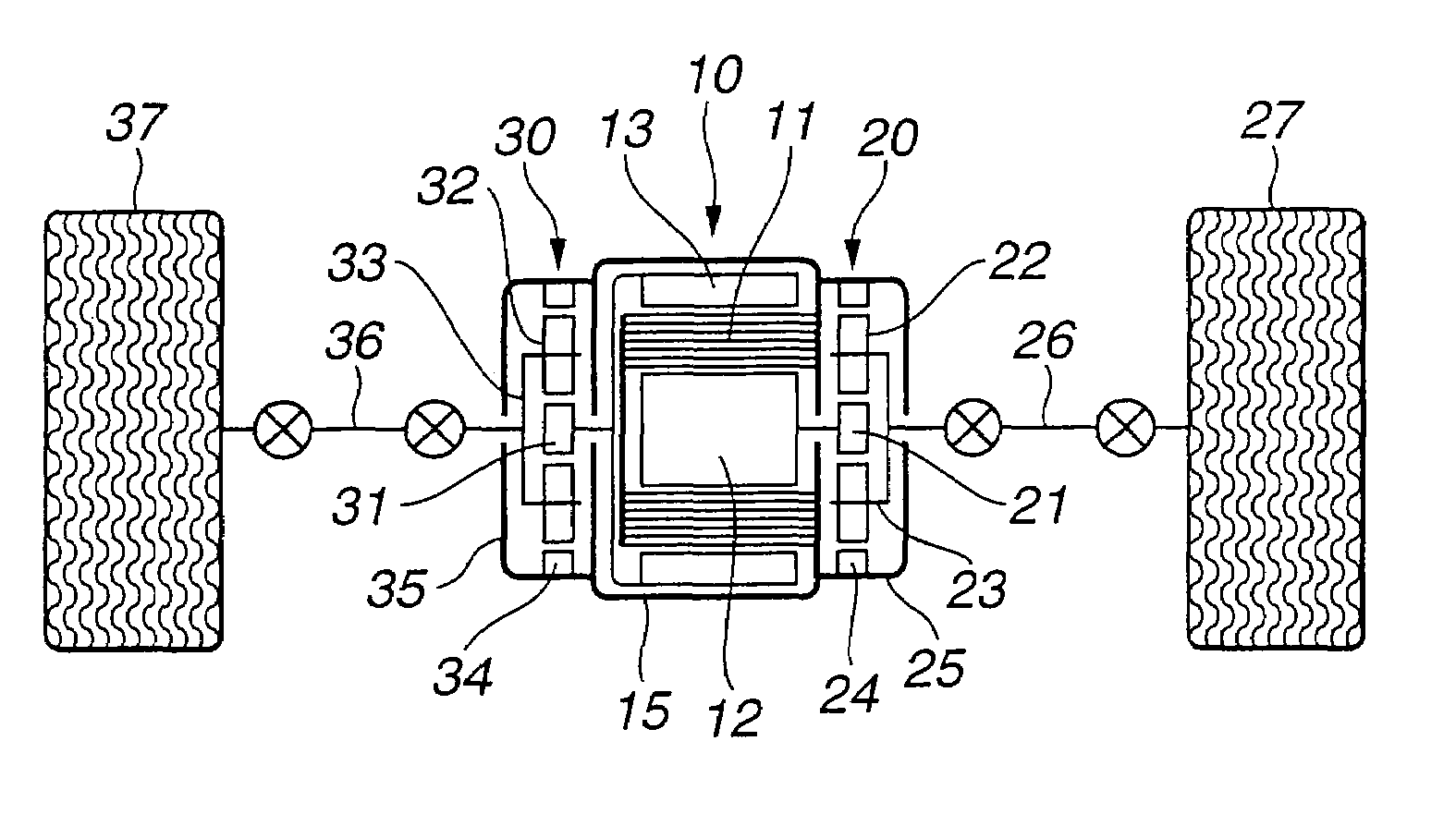
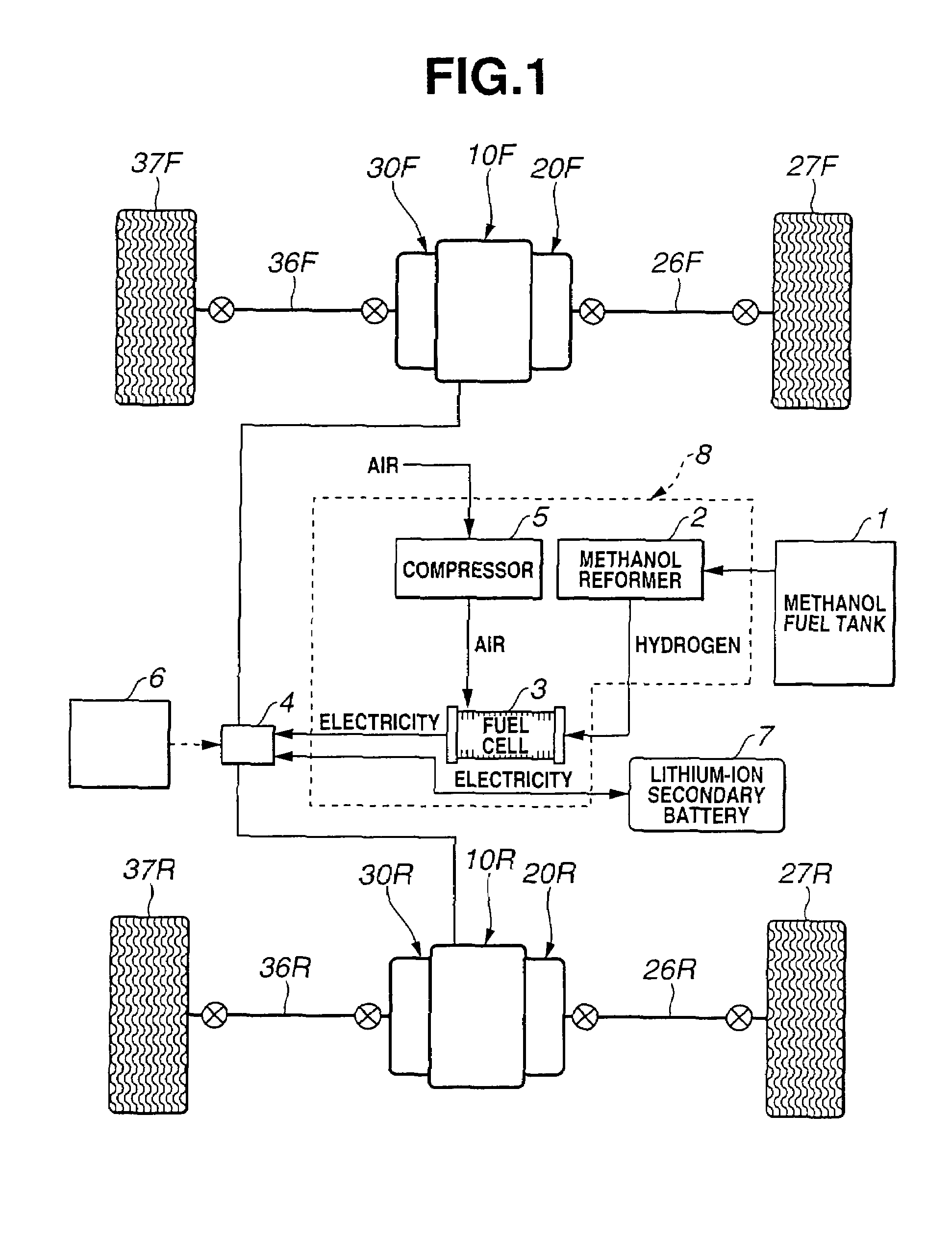
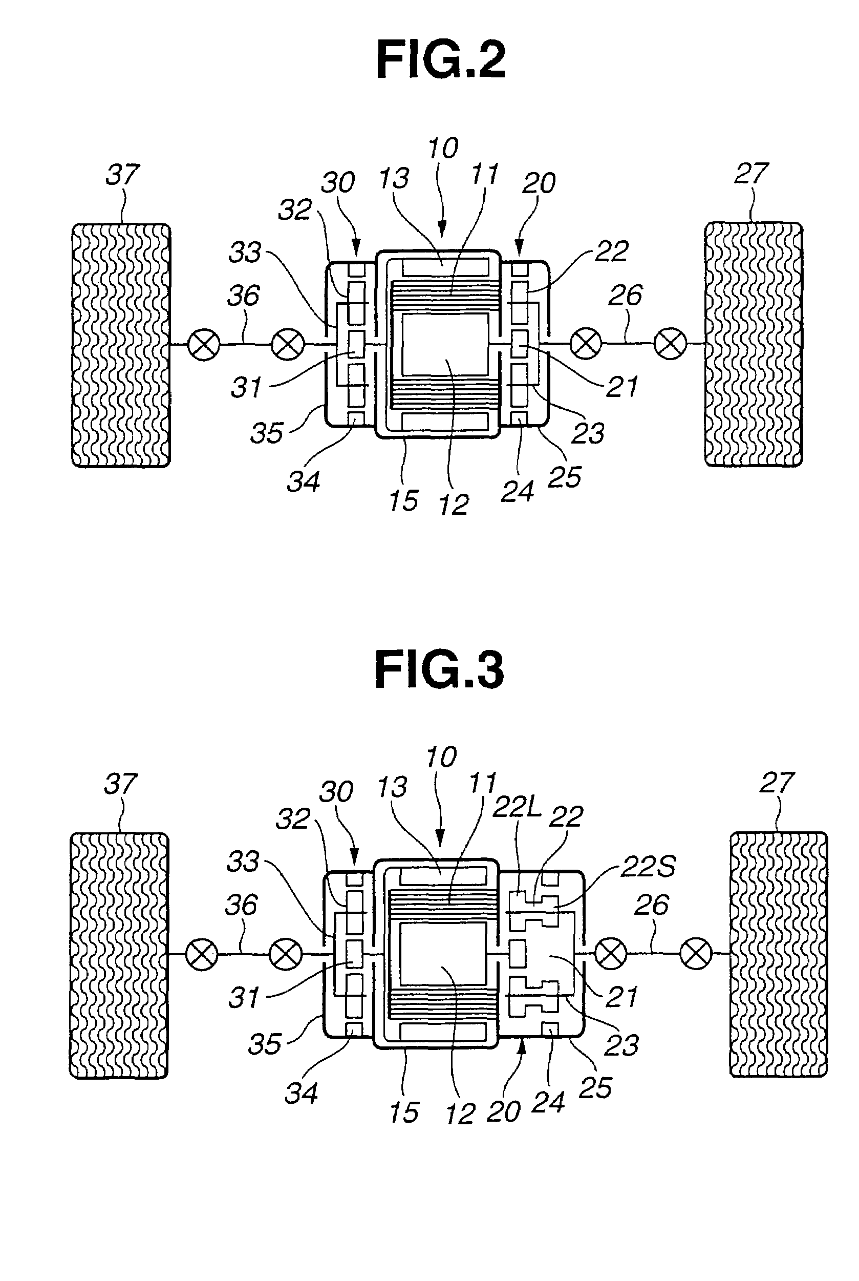
[0015]Referring to FIGS. 1 and 2, there is discussed a first embodiment of the wheel drive system according to the present invention. As shown in FIG. 1, a fuel cell vehicle employs the wheel drive system for a vehicle of a first embodiment according to the present invention. The wheel drive system is disposed between front right and left wheels 27F and 37F and between rear right and left wheels 27R and 37R. A front wheel drive system of the wheel drive system comprises a coaxial three-layer motor 10F, a first planetary gear reduction mechanism 20F, a second planetary gear reduction mechanism 30F, a first drive shaft 26F and a second drive shaft 36F. Similarly, a rear wheel drive system of the wheel drive system comprises a coaxial three-layer motor 10R, a first planetary gear reduction mechanism 20R, a second planetary gear reduction mechanism 30R, a first drive shaft 26R and a second drive shaft 36R.
[0016]Further as shown in FIG. 1, a fuel cell system for applying motor drive curr...
second embodiment
[0047]Referring to FIG. 3, there is discussed a second embodiment of the wheel drive system according to the present invention. The second embodiment is basically the same as the first embodiment except that first planetary gear reduction mechanism 20 is constructed by a compound planetary gearset.
[0048]More specifically, as shown in FIG. 3, first planetary gear reduction mechanism 20 is constructed by a compound planetary gearset which comprises stepped pinions each of which is constructed by integrally connecting a large-diameter pinion 22L meshed with a sun gear 21 and a small-diameter pinion 22S meshed with a ring gear 24. Second planetary gear reduction mechanism 30 employed in the second embodiment is the same as that of the first embodiment. That is, second planetary gear reduction mechanism 30 of the second embodiment is constructed by a simple planetary gearset which comprises a sun gear 31, a pinion carrier 33 and a ring gear 34. Ring gears 24 and 34 are fixed to reducer c...
third embodiment
[0052]There is discussed a third embodiment of the wheel drive system according to the present invention with reference to FIG. 4. The third embodiment is arranged such that both of first and second planetary gear reduction mechanisms 20 and 30 are constructed by compound planetary gearsets each of which comprises stepped pinions 22, 23.
[0053]More specifically, as shown in FIG. 4, each of first and second planetary gear reduction mechanisms 20 and 30 is constructed by a compound planetary gearset which comprises stepped pinions 22, 32 each of which is constructed by integrating large-diameter pinion 22L, 32L meshed with sun gear 21, 31 and small-diameter pinion 22S, 32S meshed with ring gear 24, 34. Sun gears 21 and 31 are connected to the output shafts, respectively. Ring gears 24 and 34 are fixed to reducer cases 25 and 35, respectively. Pinion carriers 23 and 33 are connected to wheels 27 and 37 through drive shafts 26 and 36, respectively. Since the other constructions of the th...
PUM
| Property | Measurement | Unit |
|---|---|---|
| reduction ratio | aaaaa | aaaaa |
| diameter | aaaaa | aaaaa |
| pressure | aaaaa | aaaaa |
Abstract
Description
Claims
Application Information
 - R&D
- Intellectual Property
- Life Sciences
- Materials
- Tech Scout
- Unparalleled Data Quality
- Higher Quality Content
- 60% Fewer Hallucinations
Browse by: Latest US Patents, China's latest patents, Technical Efficacy Thesaurus, Application Domain, Technology Topic, Popular Technical Reports.
© 2025 PatSnap. All rights reserved.Legal|Privacy policy|Modern Slavery Act Transparency Statement|Sitemap|About US| Contact US: help@patsnap.com


