Paravalvular leak detection, sealing, and prevention

a technology of paravalvular leakage and leak detection, applied in the field of paravalvular leak detection, sealing and prevention, can solve the problems of machiraju schreck also and amplatz not addressing leaks that can occur around the implanted valv

Active Publication Date: 2007-10-02
EDWARDS LIFESCI PVT
View PDF218 Cites 749 Cited by
  • Summary
  • Abstract
  • Description
  • Claims
  • Application Information

AI Technical Summary

Benefits of technology

[0023]Furthermore, in accordance with another preferred embodiment of the present invention, the distal end of the stent-delivery catheter is substantially perpendicular to the wall of the vessel at a point inside the cavity and the stent guidewire terminates in an anchoring mechanism that is inserted through the catheter and into the vessel wall, anchoring itself in the vessel wall and providing greater anchorage for the stent.
[0030]Also provided in accordance with a preferred embodiment of the present invention is a catheter-delivered assembly for sealing cavities occurring between a prosthetic valve and the wall of the body vessel where the valve is implanted, the cavities producing paravalvular leaks during diastole. The assembly is delivered via guidewire to the cavity and comprises two sealing stents connected by a suture, the suture running back up the catheter, the sealing stents comprising a stent structure and sealing membrane. One stent of the assembly is inserted underneath the cavity and the other stent is inserted inside the cavity, the membranes preventing the passage of fluids through the stent, thereby sealing the cavity and each stent helping anchor the other in place.

Problems solved by technology

Machiraju does not address leaks that can occur around the implanted valve.
Schreck also does not address leaks that can occur around the implanted valve.
Amplatz also does not address leaks that can occur around the implanted valve.
In addition, Amplatz's braided structures are of a shape and size not appropriate for paravalvular leak detection and sealing.
Their geometry is designed for the conditions of the transceptal hole and not appropriate for valve leakage.
Spenser et al. also do not address leaks that can occur around the implanted valve.
With both methods paravalvular leaks are a known side effect.

Method used


Image

  • Paravalvular leak detection, sealing, and prevention
  • Paravalvular leak detection, sealing, and prevention
  • Paravalvular leak detection, sealing, and prevention

Examples


Embodiment Construction

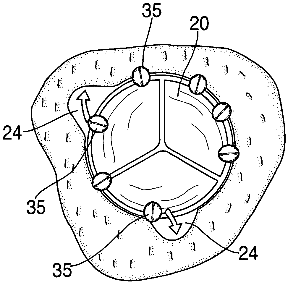
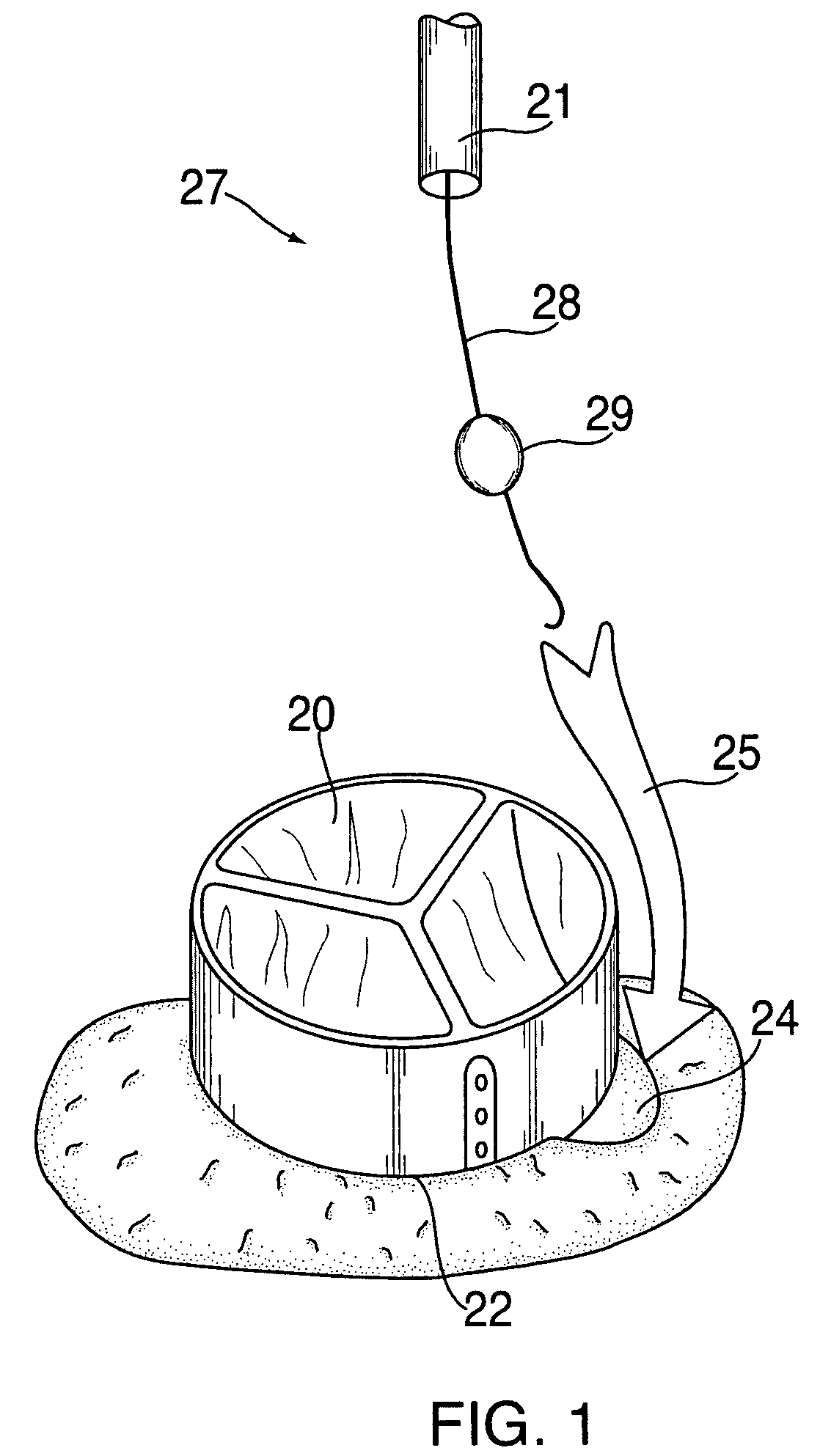
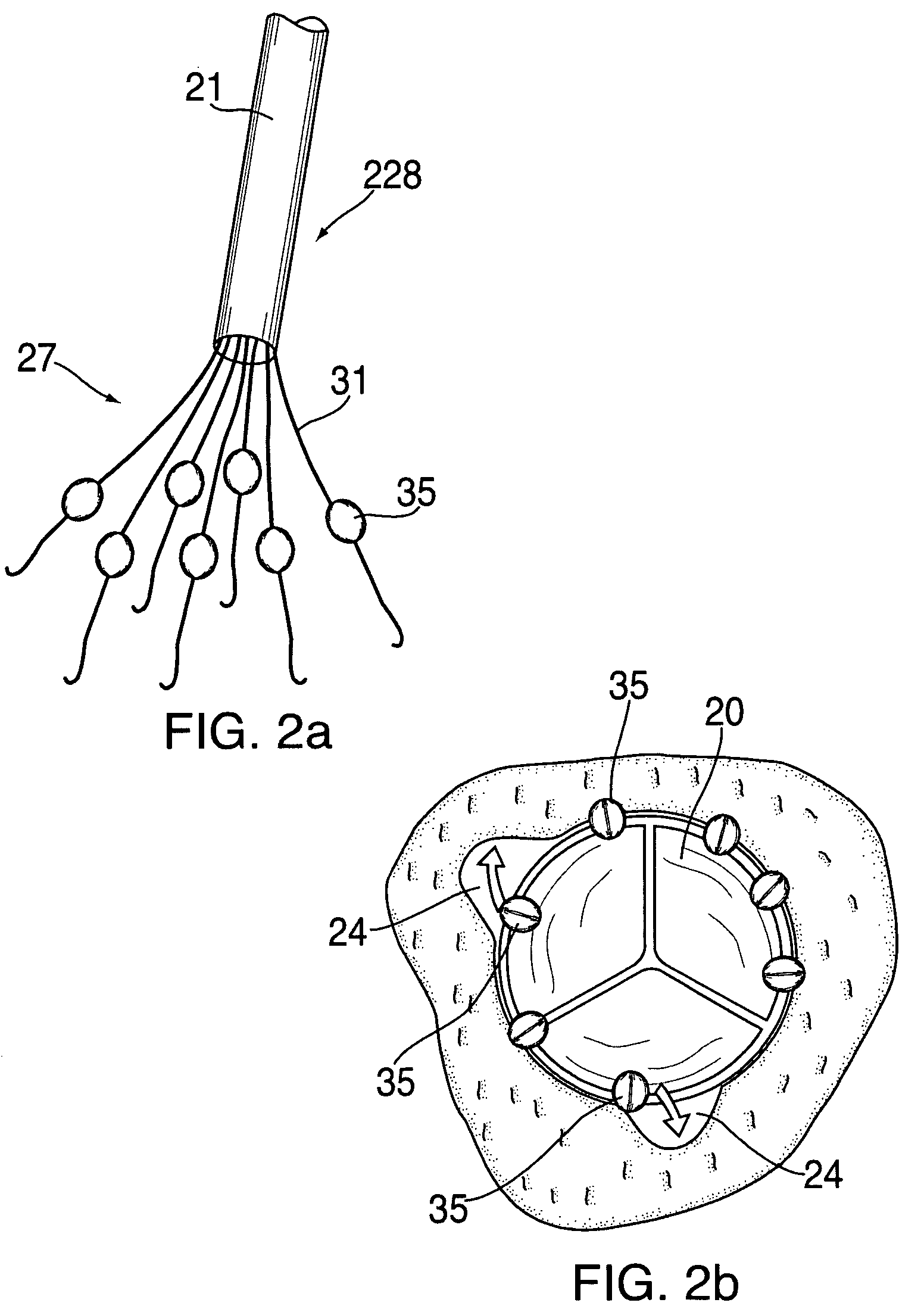
[0082]The present invention provides methods and apparatuses for substantially reducing or effectively eliminating the deleterious effects of paravalvular leaks in prosthetic valves. More specifically, it enables locating, sealing, and preventing paravalvular leaks using both dedicated and integrated (with the valve) means.

[0083]While the present invention is particularly suited for prosthetic heart valve leaks, such as a prosthetic aortic valve, it can also be applied to other leakage problems such as in other blood vessels, a septum, or other body lumens. Similarly, while the prosthetic valve described herein are tricuspid valves, it could be another type of valve as well.

[0084]A main aspect of the present invention is the introduction of several novel designs and methods for locating paravalvular leaks in prosthetic valves.

[0085]Another main aspect of the present invention are several novel designs for sealing paravalvular leaks detected in prosthetic valves.

[0086]Another main as...


PUM


Abstract

The present invention provides a series of new percutaneous concepts of paravalvular repairs including identifying the leak location, several repair techniques and finally built-in means for leak prevention, built on percutaneous valves. A catheter-delivered device locates cavities occurring between a prosthetic valve and the wall of the body vessel where the valve is implanted, the cavities producing paravalvular leaks during diastole, the device comprising at least one of a plurality of flexible wires, the wire having attached to it a balloon, wherein the balloon is pulled by the leak through the cavity and wherein the wire then serves to mark the cavity location.

Description

FIELD OF THE INVENTION[0001]The present invention relates to implantable devices. More particularly it relates to the prevention, detection, and repair of paravalvular leaks around cardiac valve prostheses.BACKGROUND OF THE INVENTION[0002]Cardiac valve implantation is well known in the art. Less well addressed is how to detect possible leaks between the valve and surrounding blood vessel, how to seal such leaks, or how to design the valve such that it automatically seals the leaks.[0003]Machiraju in U.S. Pat. No. 5,554,184, entitled “HEART VALVE”, describes a heart valve and a technique for effecting valve replacement or repair, which partially or completely replaces the mitral (or tricuspid) valve with an autologous graft from the pericardium, fascia lata or even the dura mater, or a bovine or porcine pericardial or other synthetic sheet material equivalent thereof, preferably in a configuration which substantially restores the original anatomy of the heart, including chordae tendi...

Claims


Application Information

Patent Timeline
Patent Type & Authority Patents(United States)
IPC IPC(8): A61F2/24
CPCA61F2/2409A61F2/2433A61F2/2472A61F2/2418A61F2250/006A61F2250/0069A61F2250/0003
Inventor SPENSER, BENJAMINBENICHOU, NETANELBASH, ASSAF
Owner EDWARDS LIFESCI PVT
Why Eureka
Try Eureka