Transmission modulation apparatus, communication apparatus and mobile wireless apparatus

a technology of transmission modulation and communication apparatus, applied in the direction of modulation, amplitude to angle modulation conversion, transmission, etc., can solve the problem of synchronization adjustment taking a long time to make timing adjustment, and achieve the effect of effectively avoiding such a delay

Active Publication Date: 2007-10-02
PANASONIC CORP
View PDF10 Cites 19 Cited by
  • Summary
  • Abstract
  • Description
  • Claims
  • Application Information

AI Technical Summary

Benefits of technology

[0014]It is an object of the present invention to provide a transmission modulation apparatus using polar modulation of two-point modulation scheme enabling timing adjustments of a BB phase modulation signal and BB amplitude modulation signal to be completed in a short time.
[0017]According to such a configuration, correction of deviation in synchronization between the baseband amplitude modulation signal and RF phase modulation signal can be implemented by the delay section correcting a delay amount of the baseband phase signal. Further, since the high-impedance section is provided that makes the PLL equivalently open loop, only when the delay section acquires synchronization between the baseband amplitude modulation signal and RF phase modulation signal, it is possible to make the PLL circuit equivalently open loop by operating the high-impedance section. By this means, the center frequency of the RF phase modulation signal does not shift when the PLL circuit is an open loop, and it is thereby possible to correct a delay amount of the phase modulation signal in an extremely short time and acquire synchronization between the baseband amplitude modulation signal and RF phase modulation signal. In other words, when the delay section makes a delay adjustment to the baseband phase modulation signal while keeping the PLL circuit closed loop, the center frequency of the RF phase modulation signal varies whenever the adjustment is made, and it takes a long time to converge the deviation in synchronization between the baseband amplitude modulation signal and RF phase modulation signal. According to the above-mentioned configuration, it is possible to avoid such a delay effectively.

Problems solved by technology

However, the inventor of the invention thought that adopting the configuration as shown in FIG. 2 results in a problem that it takes a time to make a timing adjustment (synchronization adjustment) to the RF phase modulation signal and BB amplitude modulation signal.

Method used


Image

  • Transmission modulation apparatus, communication apparatus and mobile wireless apparatus
  • Transmission modulation apparatus, communication apparatus and mobile wireless apparatus
  • Transmission modulation apparatus, communication apparatus and mobile wireless apparatus

Examples


embodiment 1

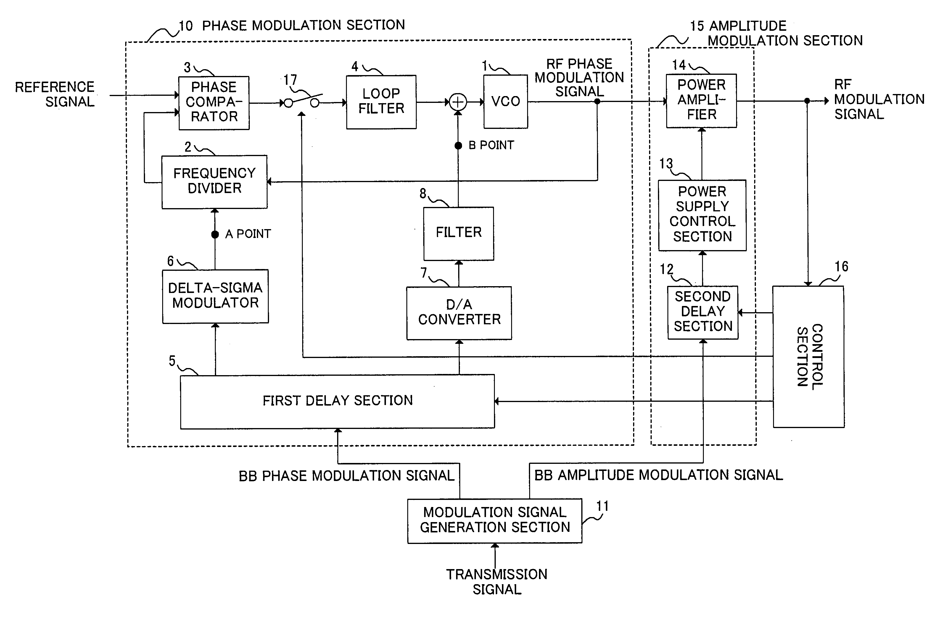
[0038]FIG. 4 is a block diagram illustrating a configuration of a transmission modulation apparatus in Embodiment 1 of the invention. The transmission modulation apparatus in Embodiment 1 of the invention as shown in FIG. 4 differs from the transmission modulation apparatus as shown in FIG. 2 in that switch (high-impedance section) 17 comprised of a semiconductor switch is provided between phase comparator 3 and loop filter 4 in phase modulation section 10, and that control section 16 outputs a control signal to switch 17. By this means, when a synchronization adjustment of a RF phase modulation signal and BB amplitude modulation signal is performed, switch 17 is turned off to make the PLL circuit open loop, so that a transient response does not occur in a signal passed through the PLL circuit at timing for adjusting a delay amount of the BB phase modulation signal, thereby enabling synchronization between the RF phase modulation signal and BB amplitude modulation signal to be acqui...

embodiment 2

[0057]FIG. 7 is a block diagram illustrating a configuration of a transmission modulation apparatus in Embodiment 2 of the invention. The transmission modulation apparatus of FIG. 8 differs from the transmission modulation apparatus of FIG. 4 in that switch 17 is removed, phase comparator 3 and loop filter 4 are directly connected making the PLL circuit closed loop, and that control section 16 outputs a control signal to phase comparator 3.

[0058]In other words, in the transmission modulation apparatus of Embodiment 1 as shown in FIG. 4, the PLL circuit is made close-loop state using switch 17. In the transmission modulation apparatus of Embodiment 2 as shown in FIG. 7, switch 17 is not provided, and when a synchronization adjustment to the RF phase modulation signal and BB amplitude modulation signal is made, an output side of phase comparator 3 is made high-impedance state with a control signal from control section 16. It is thereby possible to make the close-loop state of the PLL ...

embodiment 3

[0059]The present invention is applicable to a configuration in which the transmission modulation apparatus as described in each of the above-mentioned Embodiments is installed in a communication apparatus or a mobile wireless apparatus (such as, for example, a cellular telephone). FIG. 8 is a block diagram showing an example of a configuration of a communication apparatus provided with the transmission modulation apparatus of the invention. The communication apparatus has a configuration provided with transmission data signal input terminal 901, amplitude / phase component extracting section 902, amplitude signal processing section 903, phase modulation section 904, nonlinear amplifying section 905, and transmission output terminal 906. The transmission modulation apparatus of the invention as described above is comprised of a combination of above-mentioned elements, where amplitude / phase component extracting section 902 corresponds to modulation signal generation section 11, amplitu...


PUM


Abstract

Provided is a transmission modulation apparatus, using polar modulation of two-point modulation scheme, capable of completing a timing adjustment of a BB phase modulation signal and BB amplitude modulation signal in a short time. A phase modulation section (10) that performs two-point modulation with a PLL circuit is provided with a switch (17) to make the PLL circuit open loop, and when a first delay section (5) corrects the deviation in synchronization between the BB phase modulation signal and BB amplitude modulation signal, the switch (17) is turned off to make the PLL circuit open loop.

Description

BACKGROUND OF THE INVENTION[0001]1. Field of the Invention[0002]The present invention particularly relates to a transmission modulation apparatus that performs two-point modulation using a PLL (Phase Locked Loop) circuit and thereby generates a RF phase modulation signal, while combines the RF phase modulation signal and an amplitude modulation signal using a high-efficient linear transmission modulator and thereby performs polar modulation, and also relates to a communication apparatus and a mobile wireless apparatus provided with the transmission modulation apparatus.[0003]2. Description of the Related Art[0004]Generally, when a linear transmission modulator is designed, it is necessary to consider a trade-off between efficiency and linearity. Recently, however, technique has been proposed for obtaining both high efficiency and linearity in a linear transmission modulator by using polar modulation for separating an input signal into a phase component and amplitude component, and p...

Claims


Application Information

Patent Timeline
Patent Type & Authority Patents(United States)
IPC IPC(8): H04L27/36H03C3/08H03C3/40
CPCH03C3/0925H03C3/0933H03C3/0941H04B1/0483H03F1/0222H03C3/095H03F2200/331
Inventor HIRANO, SHUNSUKE
Owner PANASONIC CORP
Why Eureka
Try Eureka