
Piezoelectric thin-film resonator, piezoelectric filter, and electronic component including the piezoelectric filter

a thin-film resonator and piezoelectric technology, applied in piezoelectric/electrostrictive/magnetostrictive devices, piezoelectric/electrostriction/magnetostriction machines, electrical apparatus, etc., can solve the problem of unfavorable temperature coefficient of frequency (tfc) and the inability to adjust

Inactive Publication Date: 2007-10-02
MURATA MFG CO LTD
View PDF22 Cites 72 Cited by
  • Summary
  • Abstract
  • Description
  • Claims
  • Application Information

AI Technical Summary

Benefits of technology

The present invention provides a piezoelectric filter with improved performance. The filter includes a substrate and multiple piezoelectric resonators, with at least one of the resonators having a higher stiffness than the piezoelectric thin-film. The base electrodes have greater adhesion strength than the first and second electrodes. The filter may also include a balanced-to-unbalanced transforming unit such as a double-mode filter, induction coil, lattice filter, balun, or transversal surface-acoustic-wave filter. The vibrating portion of the piezoelectric thin-film is preferably located above a hollow portion in the substrate. The piezoelectric resonators may have an insulating layer with different temperature coefficients or different inducing mechanisms. The filter may be arranged in a ladder or lattice configuration. The technical effects of the invention include improved performance, reduced size, and improved stability of the piezoelectric filter.

Problems solved by technology

However, the thickness of the piezoelectric substrate can be reduced only within limits of mechanical strength and handling, and a practical high-frequency limit is several hundred MHz in a fundamental mode.
However, in the piezoelectric resonator according to reference 5, the filter characteristics widely vary and high manufacturing precision is required, which leads to an increase in the manufacturing cost.
On the other hand, because the piezoelectric resonator shown in reference 4 includes Mo and AlN, the temperature coefficient of frequency (TFC) is unfavorable and the TFC cannot be adjusted.
The filter disclosed in U.S. Pat. No. 6,323,744 has a problem in that, because input and output terminals are unbalanced terminals, the filter is not applicable to an electronic component, such as an integrated circuit, having balanced input and output terminals, which are becoming the mainstream.
Therefore, acoustic transformation is performed twice, so that transformation energy loss is increased and insertion loss is thus increased.

Method used


Image

  • Piezoelectric thin-film resonator, piezoelectric filter, and electronic component including the piezoelectric filter
  • Piezoelectric thin-film resonator, piezoelectric filter, and electronic component including the piezoelectric filter
  • Piezoelectric thin-film resonator, piezoelectric filter, and electronic component including the piezoelectric filter

Examples


Embodiment Construction

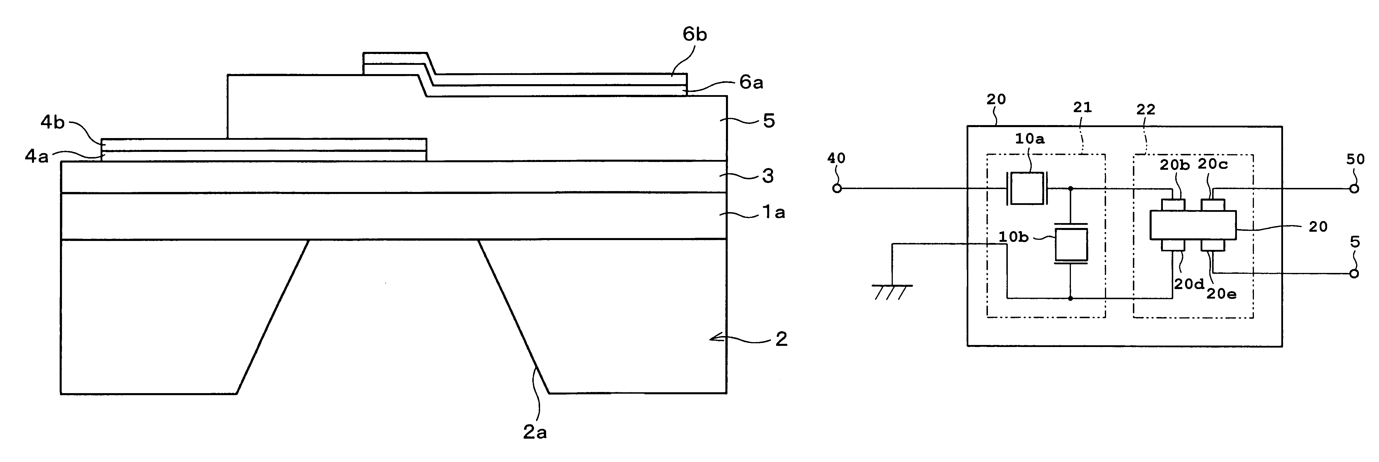
[0056]Hereinafter, preferred embodiments of the present invention including a piezoelectric thin-film resonator, a piezoelectric filter including the resonator, and a duplexer defining an electronic component including the filter of various other preferred embodiments of the present invention will be described with reference to FIGS. 1 to 19.

[0057]First Preferred Embodiment

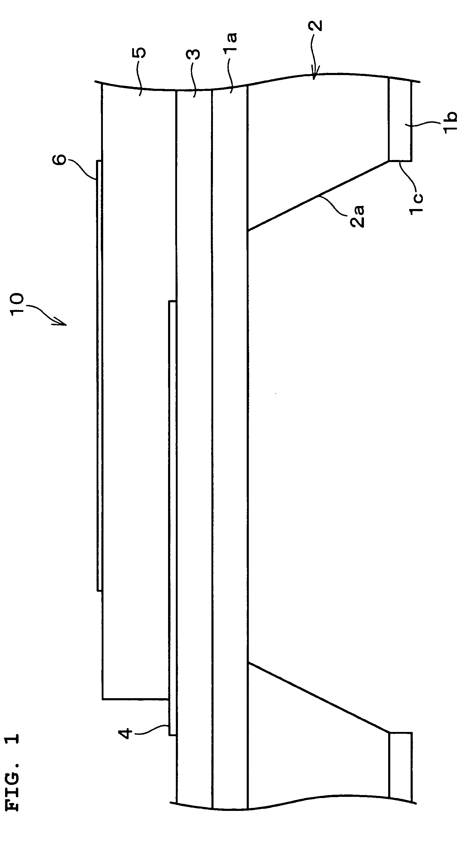
[0058]A method of manufacturing a piezoelectric thin-film resonator 10 according to the first preferred embodiment of the present invention will be described with reference to FIG. 1.

[0059]First, silicon dioxide (SiO2) films 1a and 1b serving as insulating films are formed on both principal surfaces of a supporting substrate 2, which includes (100)-oriented silicon, by thermal oxidation or sputtering. Then, a substantially rectangular window 1c, which has an edge that is substantially parallel to the (110)-direction, is formed in the SiO2 film 1b on the rear surface of the supporting substrate 2. By using the SiO2...


PUM


Abstract

A piezoelectric thin-film resonator includes a supporting substrate. A piezoelectric thin-film is formed on the supporting substrate. A lower electrode and an upper electrode are formed with the piezoelectric thin-film therebetween. The stiffness of at least one of the lower and upper electrodes is higher than that of the piezoelectric thin-film.

Description

[0001]This application is a Continuation-in-Part of U.S. patent application Ser. No. 10 / 456,173, filed on Jun. 6, 2003, now U.S. Pat. No. 7,002,437.BACKGROUND OF THE INVENTION[0002]1. Field of the Invention[0003]The present invention relates to a piezoelectric thin-film resonator used for filters in a high-frequency band (RF band, particularly, GHz band or more) of communication apparatuses, such as mobile phones. The present invention also relates to a piezoelectric filter including the resonator and an electronic component including the piezoelectric filter, such as a duplexer.[0004]2. Description of the Related Art[0005]In recent years, filters used in a high-frequency band (RF band, particularly, GHz band or more) for use in communication apparatuses, such as mobile phones, have been developed by using piezoelectric resonators that are small, lightweight, and highly resistant to vibration and shock. Furthermore, variations in products are small, highly reliable, and circuits nee...

Claims


Application Information

Patent Timeline
Patent Type & Authority Patents(United States)
IPC IPC(8): H03H9/54H03H9/15H03H9/00H03H9/02H03H9/17H03H9/56H03H9/58H03H9/60
CPCH03H9/0095H03H9/02094H03H9/02102H03H9/60H03H9/174H03H9/586H03H9/588H03H9/02133H03H9/131
Inventor TAKEUCHI, MASAKIYAMADAKAWAMURA, HIDEKINAKAMURA, DAISUKEYOSHINO, YUKIOGOTOH, YOSHIHIKOARAI, SEIICHI
Owner MURATA MFG CO LTD
Learn More