Accelerator pedal module

a pedal module and accelerator technology, applied in the direction of mechanical control devices, instruments, process and machine control, etc., can solve the problems of affecting the rigidity of the bearing of the transducer shaft and hence the measurement accuracy of the rotation sensor, and the arrangement is complex and expensive to produce, so as to reduce the effort and expense of assembly.

Inactive Publication Date: 2007-10-09
ROBERT BOSCH GMBH
View PDF15 Cites 19 Cited by
  • Summary
  • Abstract
  • Description
  • Claims
  • Application Information

AI Technical Summary

Benefits of technology

[0012]Preferably, the driver is formed by a driver pin, which is embraced with prestressing in a recess in the pedal lever or in the bearing block. This is realized for instance by providing that the recess is formed by a blind bore, whose cross section is slightly smaller than the cross section of the driver pin, and at least one side wall of the blind bore is elastically deformable upon introduction of the driver pin. Because of the prestressing, this connection is very rigid, resulting in a play-free transmission of the motion of the pedal lever to the sensor shaft. Because the restoring spring system for restoring the pedal lever tenses the bearing faces of the pedal lever against the bearing faces of the bearing block, the driver is also tensed in the radial direction into the receptacle at the same time, and because additional retaining and connecting elements between the driver and the pedal lever and between the driver and the bearing block are dispensed with, the effort and expense of assembly are greatly reduced.

Problems solved by technology

However, this arrangement is complex and expensive to produce.
Moreover, a number of parting seams subject to variation occur between the components inserted radially into one another, which adversely affects the rigidity of the bearing of the transducer shaft and hence also the measurement accuracy of the rotation sensor.

Method used


Image

  • Accelerator pedal module
  • Accelerator pedal module
  • Accelerator pedal module

Examples


Embodiment Construction

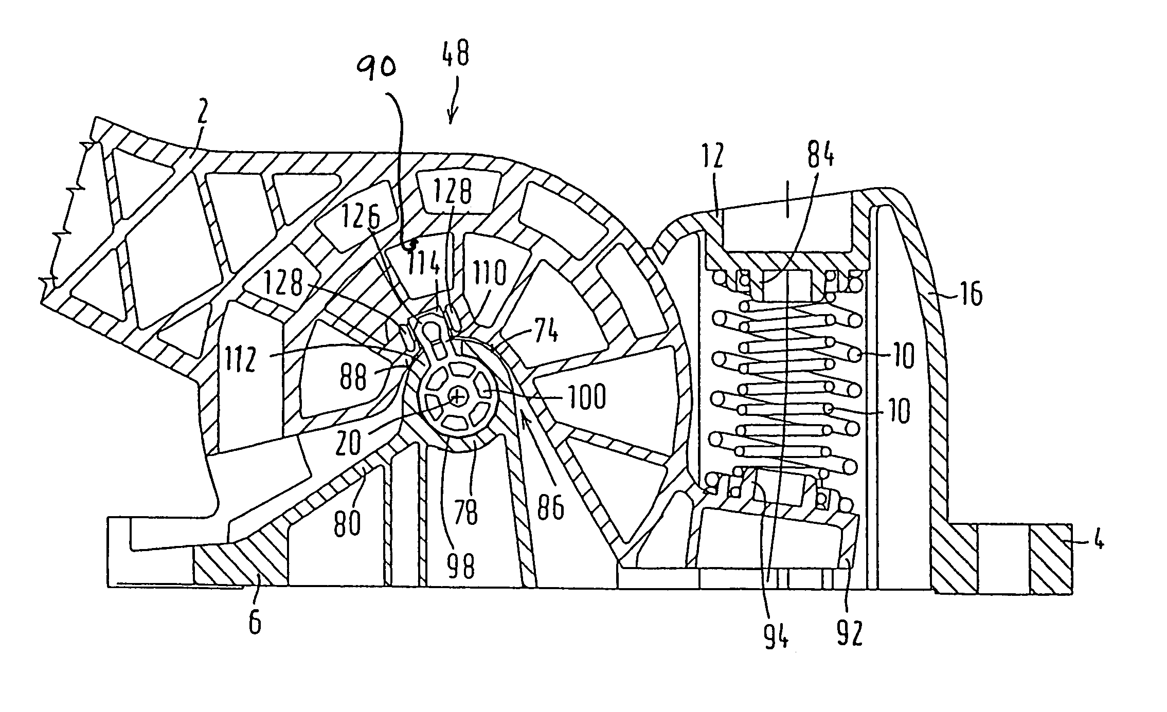
[0021]The accelerator pedal module of the invention is used for controlling a driving engine, preferably an internal combustion engine of a motor vehicle, whose throttle valve is adjustable by a control motor. In that case, the accelerator pedal module serves to generate electrical signals for the control motor, so that the engine power can be controlled as a function of the position of an accelerator pedal of the accelerator pedal module. However, the driving engine can also for instance be an electric motor that is triggered by electrical signals.

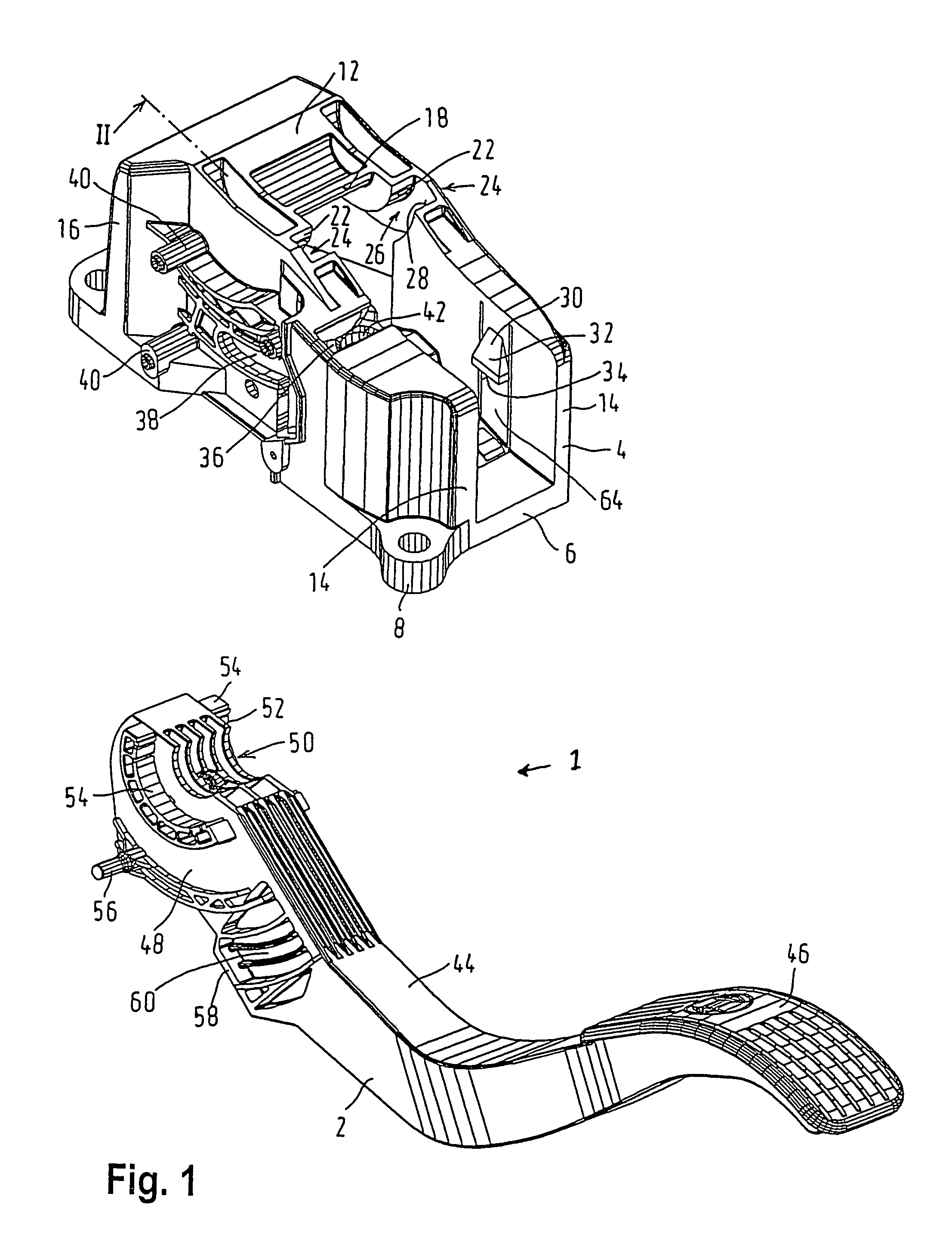
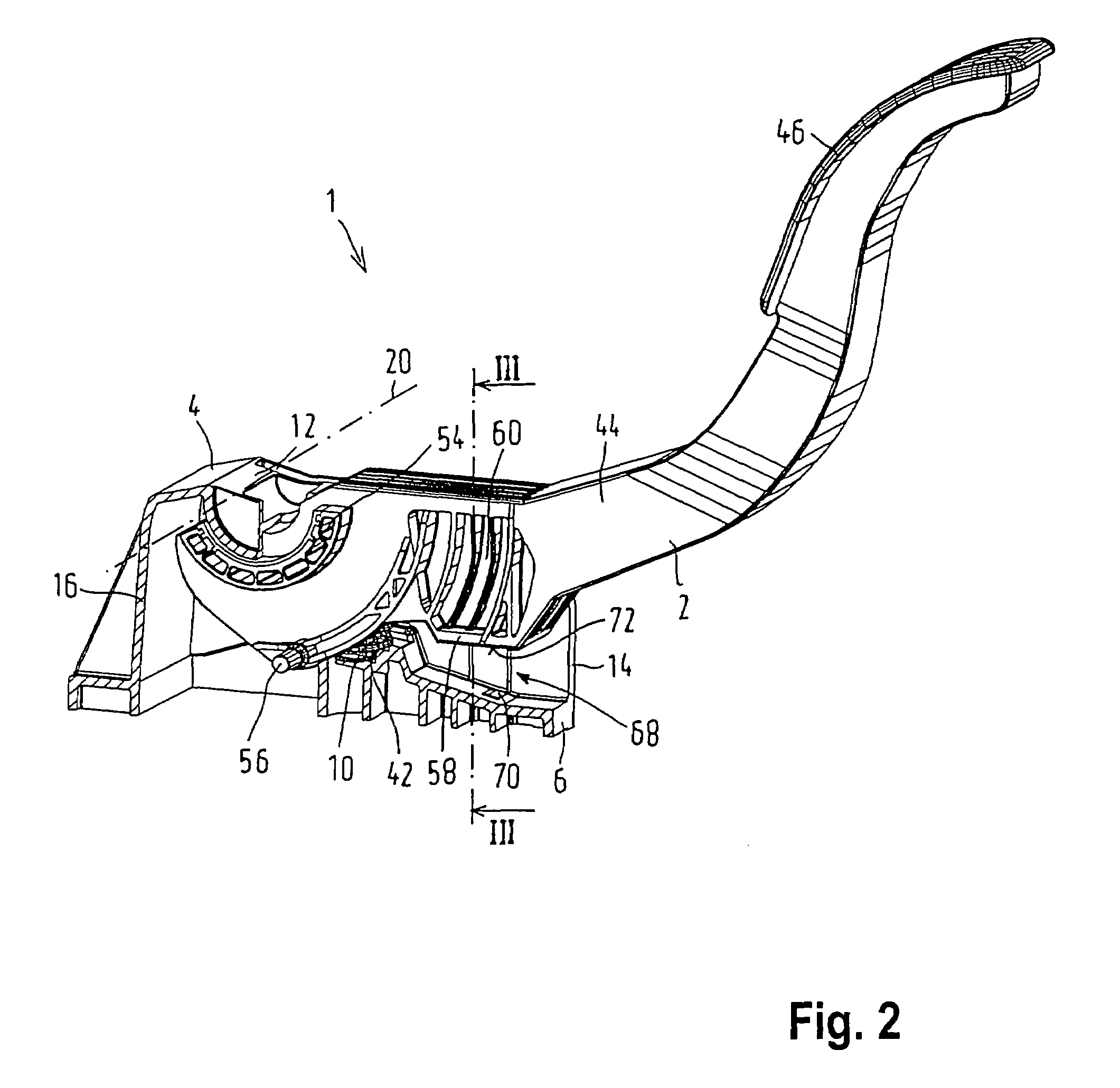
[0022]The accelerator pedal module 1 is foot-actuated by the motor vehicle's driver and as shown in FIG. 1 includes a pedal lever 2, which preferably is the gas pedal actuated directly by the driver's foot. Alternatively, the pedal lever 2 can be a lever of a lever mechanism or rod linkage mechanism that includes additional levers and is coupled to the gas pedal. The accelerator pedal module 1 also includes a bearing block 4 as a retentio...


PUM


Abstract

The invention relates to an accelerator pedal module for controlling the power of a driving engine having a pedal lever which is retained rotatably about a pivot axis on a bearing block and which actuates a sensor shaft of a rotation sensor, the sensor shaft being coaxial with the pivot axis. At least a part of the sensor shaft is directly supported rotatably in a bearing bore of a bearing region that is integral with the bearing block, of which bearing region at least a part of the radially outer circumferential surface forms at least one bearing face for the pedal lever.

Description

BACKGROUND OF THE INVENTION[0001]1. Field of the Invention[0002]The invention is directed to an improved accelerator pedal module for controlling the power of a driving engine, in particular an internal combustion engine of a vehicle, having a pedal lever which is retained rotatably about a pivot axis on a bearing block and which actuates a sensor shaft of a rotation sensor, the sensor shaft being coaxial with the pivot axis.[0003]2. Description of the Prior Art[0004]One known accelerator pedal module is described in German Patent DE 195 31 735 C1. In the known accelerator pedal, a transducer shaft of the rotation sensor is rotatably supported in a slide bush that is retained within a bearing bush. Loops of two cables are disposed in turn between the bearing bush and a radially inner circumferential wall of a bearing bore of the pedal lever and are coupled with reverse-tension springs that serve to restore the pedal lever to an idling position. However, this arrangement is complex a...

Claims


Application Information

Patent Timeline
Patent Type & Authority Patents(United States)
IPC IPC(8): G05G1/30B60K26/02F02D11/02G05G5/03
CPCB60K26/02F02D11/02G05G5/03G05G1/30Y10T74/20888Y10T74/20534
Inventor SOLTA, ROSTISLAV
Owner ROBERT BOSCH GMBH
Why Eureka
Try Eureka