Concrete-block-making machine

a concrete block and machine technology, applied in dough shaping, baking, food shaping, etc., can solve the problems of affecting the linear drive of the filling carriage, affecting the accuracy of the filling, etc., and achieving the effect of reducing the number of fillings

Inactive Publication Date: 2007-10-09
HESS MASCHFAB
View PDF11 Cites 9 Cited by
  • Summary
  • Abstract
  • Description
  • Claims
  • Application Information

AI Technical Summary

Benefits of technology

[0003]An object of the invention is to provide a concrete-block-making machine wherein the block quality is practically not impaired by the dusty environment and corresponding play between moving part and guide.
[0004]Owing to the fact that according to the invention a linear guide is used which comprises at least one guide rod for guide rollers of the part to be moved, in particular of the filling carriage, the at least one guide rod and the guide rollers movably guided relative thereto being hardened, the guide becomes insensitive to dust despite the smallest possible play, since this achieves the effect that dust deposited on the at least one guide rod is rolled and thereby flattened between the guide rod and the guide rollers by the movement of the guide rollers along the guide rod. In this way, the linear guide cleans itself automatically, the hardening of the parts guided in engagement with one another preventing damage to said parts due to the dust. This enables a linear motor to be used as drive unit, since a small air gap between primary part and secondary part, as is required in a linear motor, can in this case be maintained with sufficient accuracy. The linear motor in turn leads to high positioning accuracy of the part to be moved, is highly dynamic and permits very high repetitive accuracy of its sequence of movement, as a result of which, in particular in the case of a filling carriage as moving part, high repetitive accuracy of the filling operation of the mould of a concrete-block-making machine and thus a correspondingly uniform block quality are obtained.

Problems solved by technology

In the process, considerable contamination occurs, which is caused by cement dust released in particular during the compacting operation and which, due to deposits, impairs the linear drive for the filling carriage and in particular the linear guide.
However, this does not permit high positioning accuracy and repetitive accuracy, which are important for a uniform block quality.

Method used


Image

  • Concrete-block-making machine
  • Concrete-block-making machine
  • Concrete-block-making machine

Examples


Embodiment Construction

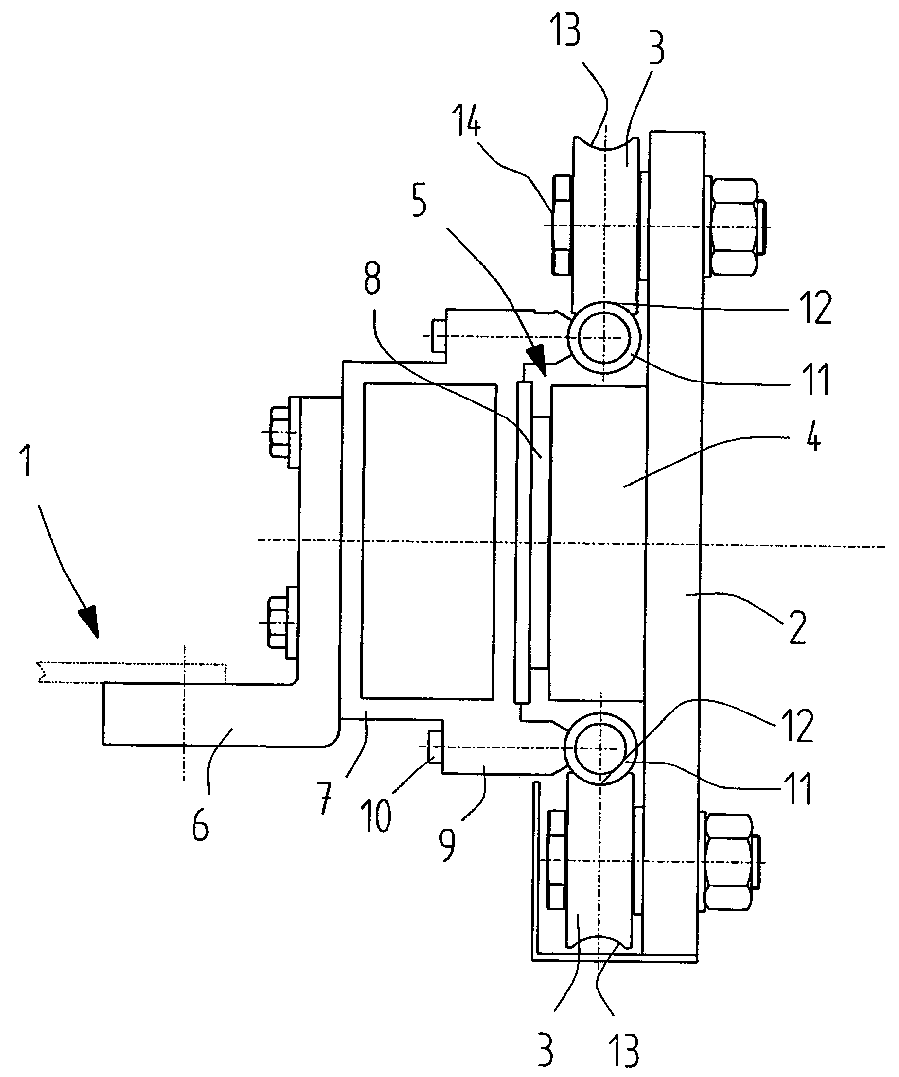
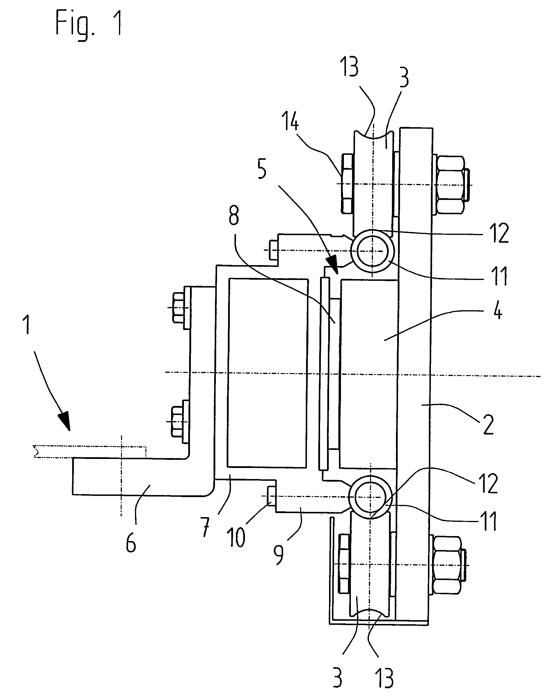
[0010]FIG. 1 shows a detail of a linear drive on one side of a filling carriage 1 of a concrete-block-making machine, although such a linear drive is provided at a filling carriage on each side thereof. The linear drive comprises a fixed cheek 2 having a plurality of top and bottom guide rollers 3. A fixed primary part 4 of a linear motor 5 (coil arrangement) is arranged on the cheek 2 between the top and bottom guide rollers 3.

[0011]At the filling carriage 1 is fastened, for example via an angle 6, a support section 7, for instance a box section in particular made of an aluminium alloy, which carries the permanently magnetic secondary part 8 of the linear motor 5 and has a length which corresponds at least to the amount of travel of the filling carriage 1 plus the length of the cheek 2. There is a slight air gap between the primary and secondary parts 4 and 8, respectively, of the linear motor 5.

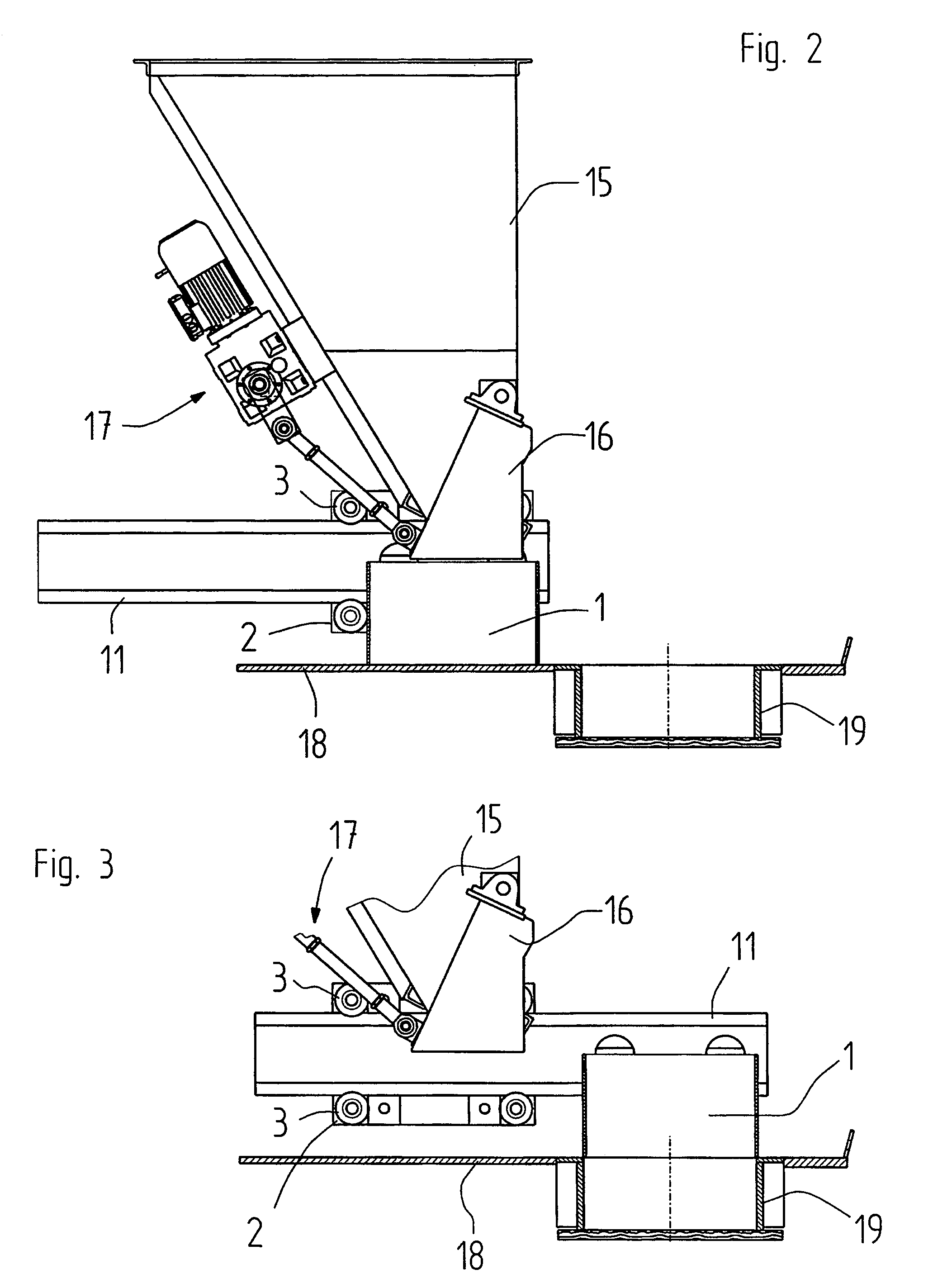
[0012]Two parallel guide rods 11 arranged at a distance apart one above the other are f...


PUM

PropertyMeasurementUnit
shapeaaaaaaaaaa
lengthaaaaaaaaaa
distanceaaaaaaaaaa

Abstract

The invention relates to a concrete-block-making machine having a part which is displaceable via a linear drive, the linear drive comprising a drive unit and a linear guide for guide rollers, the drive unit comprising at least one linear motor and the linear guide comprising at least one guide rod for the guide rollers, the at least one guide rod and the guide rollers movable relative thereto being hardened, and guide rollers and guide rod being arranged with slight play relative to one another.

Description

FIELD OF THE INVENTION[0001]The invention relates to a machine for producing concrete blocks for constructional purposes.BACKGROUND OF THE INVENTION[0002]For the production of concrete blocks, concrete-block-making machines are used in which a mould is filled with concrete mortar by means of a filling carriage. In this case, the filling carriage with the concrete mortar is moved horizontally right across the mould, so that the concrete mortar can fall into the mould. The filling carriage, open at the top and bottom and located below a silo, is filled in the process and moved by means of a linear drive across a table plate into a position above the mould located on a production base. In this case, the filling carriage is guided by a horizontal guide. In the process, considerable contamination occurs, which is caused by cement dust released in particular during the compacting operation and which, due to deposits, impairs the linear drive for the filling carriage and in particular the ...

Claims


Application Information

Patent Timeline
Patent Type & Authority Patents(United States)
IPC IPC(8): B28B17/00B28B13/02B30B15/30
CPCB30B15/304B28B13/023
Inventor KRAUSE, ROLANDBACKS, ULRICH
Owner HESS MASCHFAB
Why Eureka
Try Eureka