Spiraltrap: devices and methods for the trapping particulate matter in exhaust and of other pollutants

a technology of particulate matter and air trapping, which is applied in the direction of liquid degasification, separation process, filtration separation, etc., can solve the problems of high cost of options above (1) and (2), different temperature throughout the cylinder, and exhaust pollution of powered vehicles, so as to reduce the amount of particulate pollution

Inactive Publication Date: 2007-10-09
INDAL WIDGET WORKS
View PDF9 Cites 11 Cited by
  • Summary
  • Abstract
  • Description
  • Claims
  • Application Information

AI Technical Summary

Benefits of technology

[0024]According to another embodiment thereof, the present invention is also a method of reducing particulate pollution from a source of particulate-containing exhaust. The method may include steps of providing a pollution reducing device, the pollution reducing device including a tube defining an internal lumen, a first free end and a second free end, and a layer of particulate absorbing material disposed within the internal lumen, the particulate absorbing material defining a helically-shaped void that extends from the first free end to the second free end; coupling the pollution reducing device to the source of exhaust, and trapping particulates from the exhaust within the particulate absorbing material.

Problems solved by technology

The major drawback to diesel powered vehicles is the exhaust pollution, which is quite different than generated from a gasoline engine.
The problem is that the temperature is not uniform throughout the cylinder and some small portions of the fuel will not burn but rather be subject to reduction (carbon-hydrogen bond broken and carbon-carbon bond formed) as well as combustion (carbon-hydrogen bond broken and carbon-oxygen and hydrogen-oxygen bonds formed).
The options above (1) and (2) are expensive; (1) will affect all diesel engines for which the modified fuel is used and (2) will affect only the new engines which incorporate this technology.

Method used


Image

  • Spiraltrap: devices and methods for the trapping particulate matter in exhaust and of other pollutants
  • Spiraltrap: devices and methods for the trapping particulate matter in exhaust and of other pollutants
  • Spiraltrap: devices and methods for the trapping particulate matter in exhaust and of other pollutants

Examples


Embodiment Construction

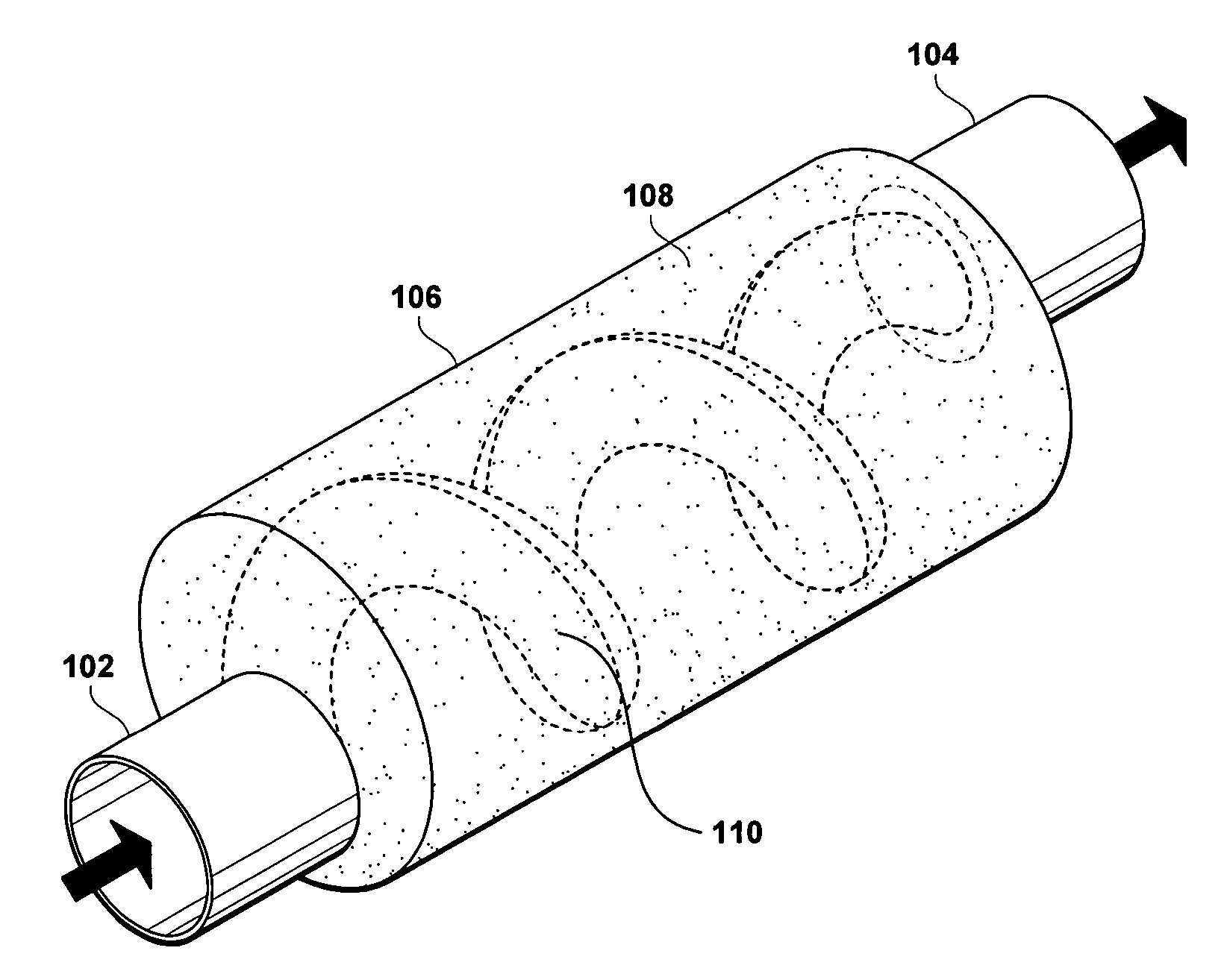
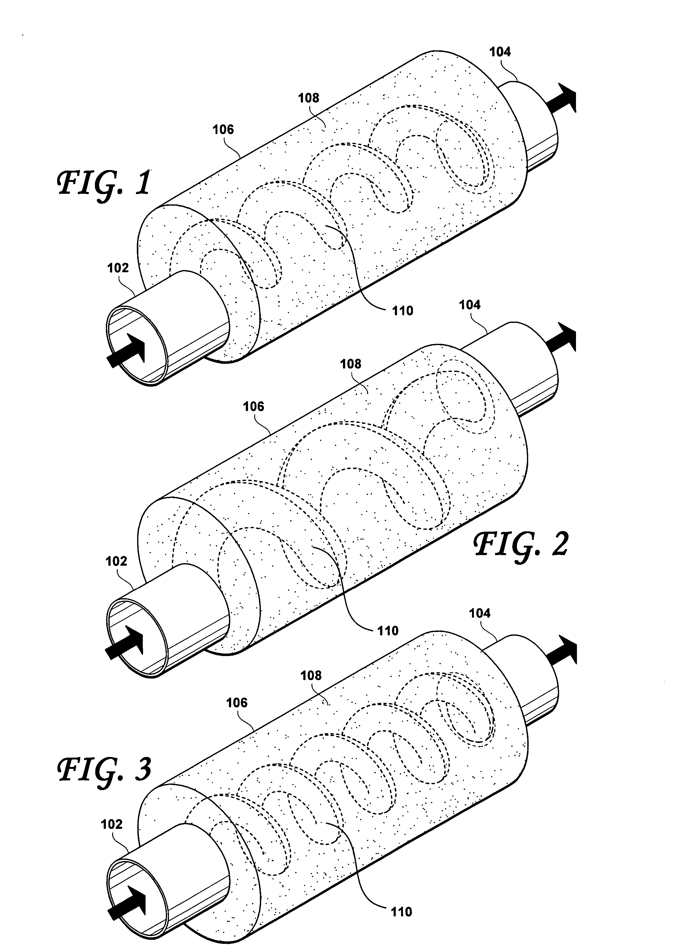
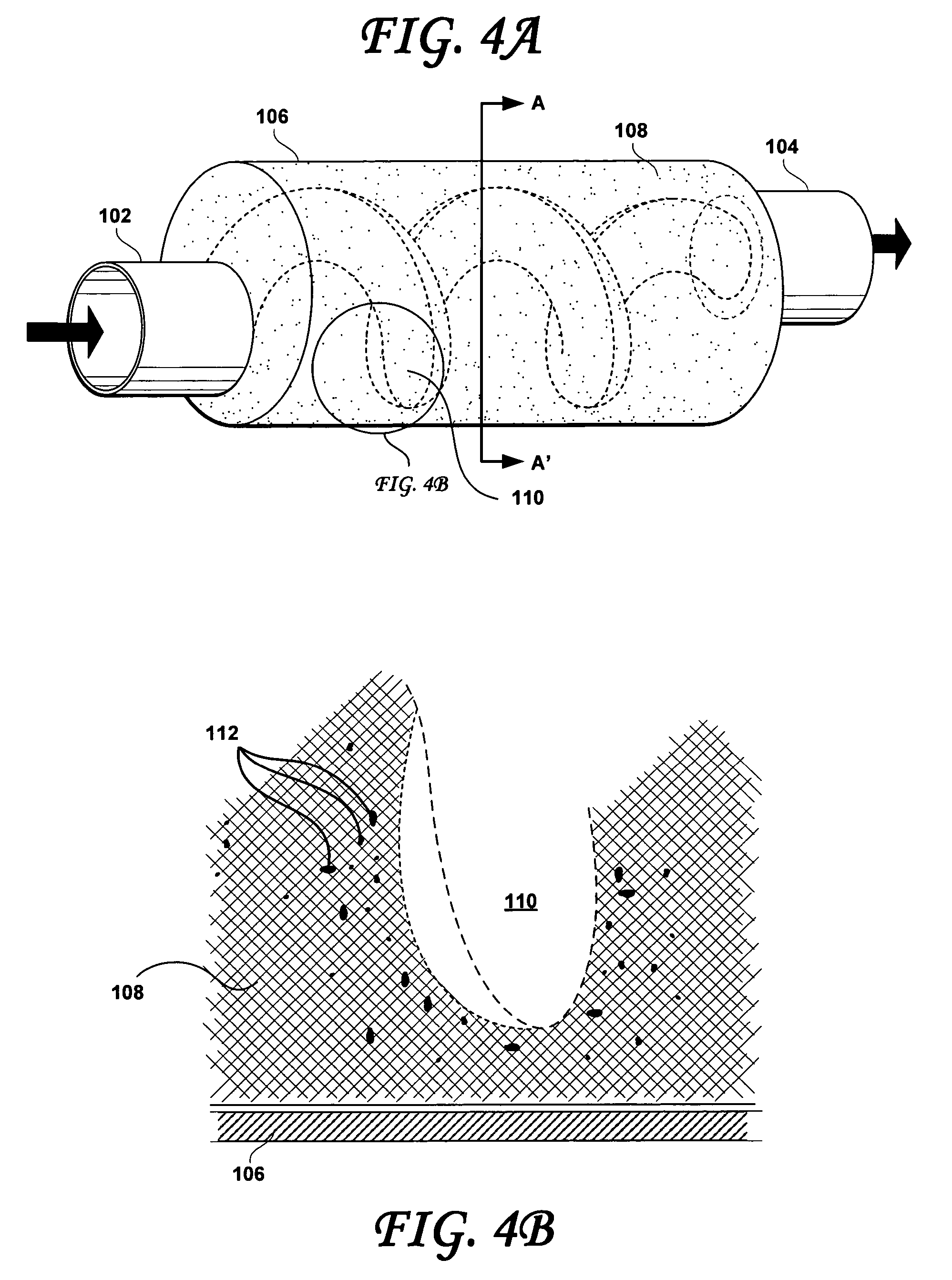
[0026]FIGS. 1-3 show different embodiments of the present invention. An embodiments of the present invention is a mechanical device with no moving parts which will channel diesel or other exhaust gases containing particulates through a (e.g., metal) tube 106 having an internal lumen that is lined with absorbing material 108 (such as a ceramic foam, for example). The absorbing material 108 lined within the lumen 110 of the tube 106 may define a void having a spiral or extended coil shape that extends from one free end of the tube (e.g., the exhaust inlet 102) to the other free end of the tube (e.g., the exhaust outlet 104). In this manner, exhaust may travel from the inlet 102 to the outlet 104 while being constrained to follow the spiral shape of the void defined by the lining of the tube. The effect of the spiral will cause the particulates suspended in the exhaust, which particulates, having more momentum than the gases, continue in a straight line, to collide with and become trap...


PUM

PropertyMeasurementUnit
porosity densityaaaaaaaaaa
temperaturesaaaaaaaaaa
ignition pointaaaaaaaaaa

Abstract

Embodiments of the present invention include methods and devices for trapping particulate matter suspended in exhaust from, for example, automotive diesel engines. Particulates carried in exhaust are actually a colloidal suspension of finely divided particulates in a fluid (in this case, the exhaust gases). This colloidal mixture is channeled through an open spiral exhaust channel. The particulates will differentially tend to travel through the fluid in a straight line, which leads them to collide with a fine mesh or porous material that defines the open spiral exhaust channel. The gas, on the other hand, will easily traverse the spirally shaped exhaust channel, with its molecules bouncing around the curved path of the spiral. Continuing through the device, more and more particulates will build up in the surrounding meshwork or porous material.

Description

[0001]This application claims the benefit under 35 U.S.C. § 119(e), of U.S. provisional application Ser. No. 60 / 646,688, filed Jan. 24, 2005, which application is hereby incorporated herein by reference in its entirety.BACKGROUND OF THE INVENTION[0002]1. Field of the Invention[0003]The present inventions relate to pollution reducing devices and methods. In particular, the present invention relates to the field of methods and devices for trapping particulate matter suspended in exhaust from, for example, an automotive diesel engine.[0004]2. Description of the Related Art[0005]Diesel engines provide very efficient power from a given amount of fuel, and they are able to use significantly less expensive fuels than gasoline engines. Thus, for trucks, buses, railroad locomotives, generators, and even automobiles, the diesel engine is preferred over the gasoline engine. The major drawback to diesel powered vehicles is the exhaust pollution, which is quite different than generated from a ga...

Claims


Application Information

Patent Timeline
Patent Type & Authority Patents(United States)
IPC IPC(8): B01D45/12B01D46/24
CPCB01D45/16F01N1/125F01N3/023F01N3/0226Y10S55/30F01N2330/102
Inventor JOHNSON, RICHARD C.
Owner INDAL WIDGET WORKS
Why Eureka
Try Eureka