Well planning using seismic coherence

Inactive Publication Date: 2007-10-09
CONOCOPHILLIPS CO
View PDF9 Cites 19 Cited by
  • Summary
  • Abstract
  • Description
  • Claims
  • Application Information

AI Technical Summary

Benefits of technology

[0008]It is, therefore, an object of the present invention to provide a method for predicting hydrocarbon production from a subterranean formation using seis

Problems solved by technology

However, many wells that exhibit high levels of initial production quickly taper off due to lack of geologic connectivity around the well.
Thus, conventional seismic coherence methods do not provide an accurate indication of the geologic connectivity of an entire field.

Method used


Image

  • Well planning using seismic coherence
  • Well planning using seismic coherence
  • Well planning using seismic coherence

Examples


Embodiment Construction

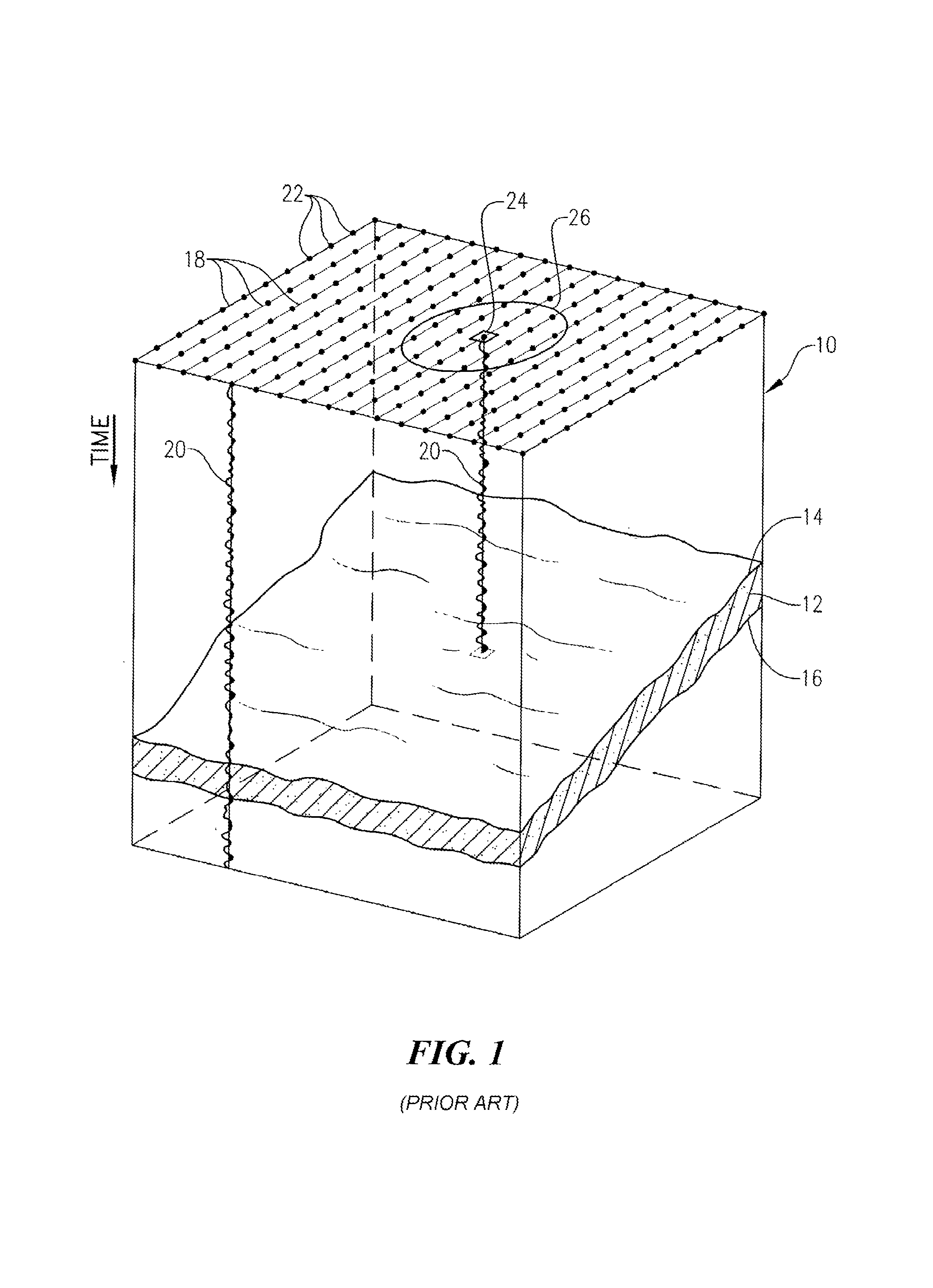
[0029]Referring initially to FIG. 1, a subterranean region of interest 10 is illustrated as containing a horizon window 12 of subsurface strata bounded by upper and lower horizons 14,16. The subsurface strata located above upper horizon 14 and below lower horizon 16 have been deleted for clarity. A 3D seismic survey has been conducted, processed, and interpreted for subterranean region of interest 10. As is well known in the art, 3D seismic data typically comprise a set of substantially parallel 2D survey lines, such as survey lines 18, each of which consists of a series of stacked seismic traces 20 (only 2 shown for clarity) located at laterally spaced positions 22 along survey line 18. Each stacked seismic trace 20 shows the two-way seismic signal travel time to the various reflection events. Time t0 typically represents the surface of the earth, although any other horizontal datum maybe used if desired.

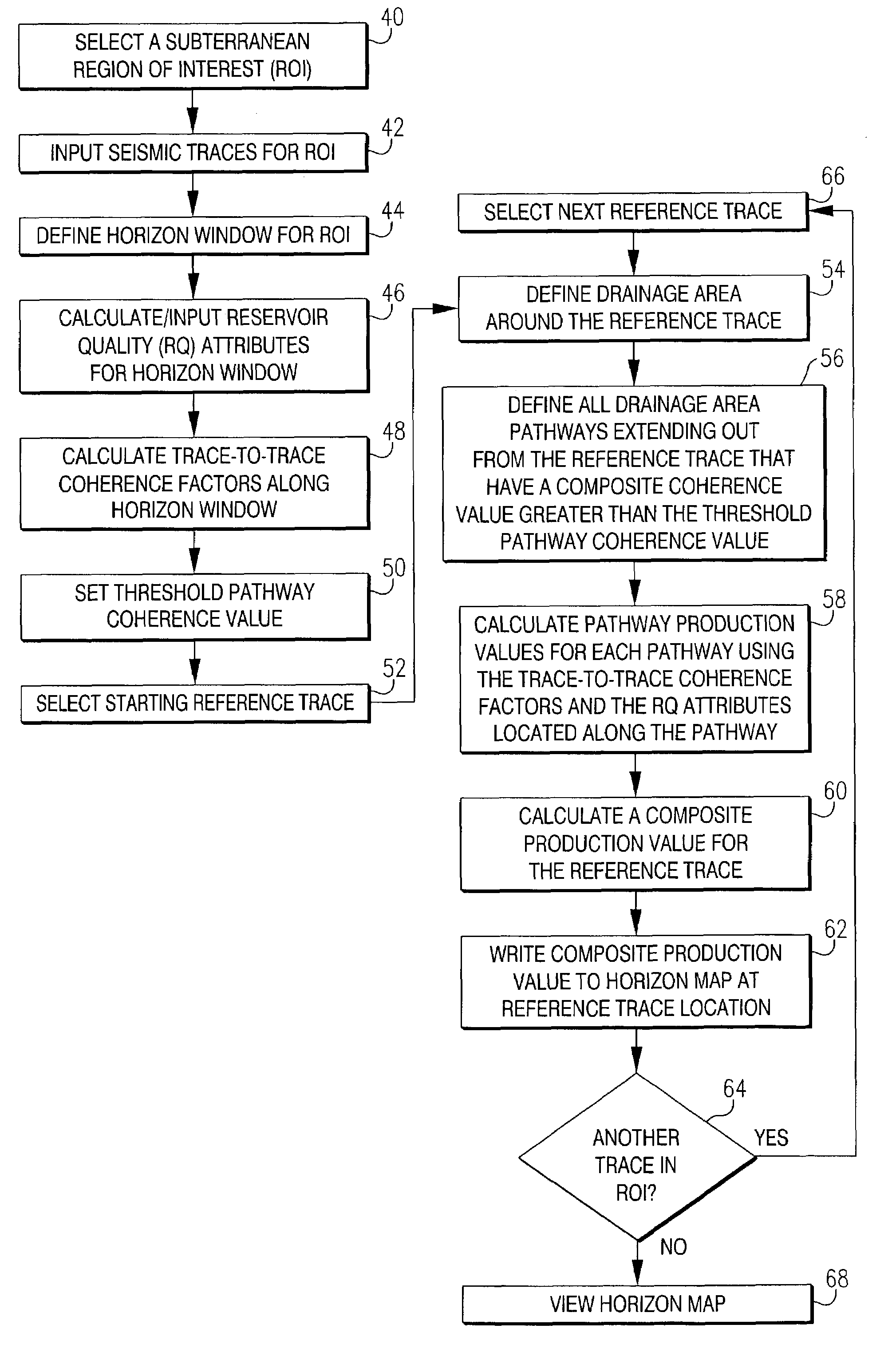
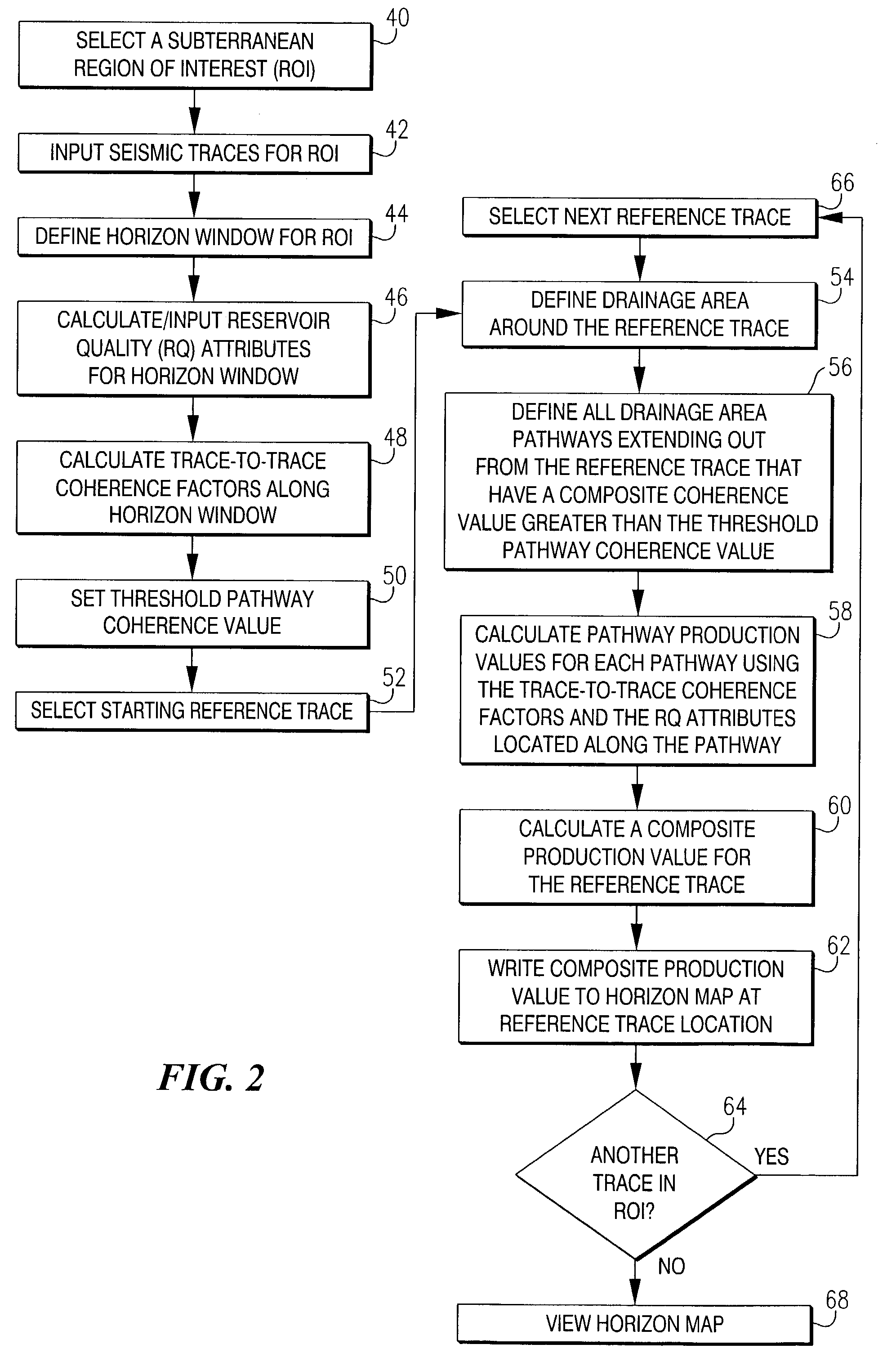
[0030]Referring to FIG. 2, in initial step 40 of the present invention, a subt...


PUM


Abstract

A system for predicting hydrocarbon production from a subterranean region of interest using reflection seismic data. The system sets a drainage area around reference traces and defines drainage pathways extending outwardly from the reference trace towards the perimeter of the drainage area. A mathematical combination of the trace-to-trace coherence factors and reservoir quality attributes along each drainage pathway is calculated for each reference trace, thereby providing an indication of both initial and sustained hydrocarbon production from that location.

Description

BACKGROUND OF THE INVENTION[0001]1. Field of the Invention[0002]The present invention relates generally to methods for predicting hydrocarbon production from a subterranean formation using reflection seismic data. In another aspect, the invention concerns a method of predicting hydrocarbon production from a subterranean formation based upon reservoir quality values and seismic coherence factors determined from reflection seismic data.[0003]2. Description of the Prior Art[0004]For many years seismic exploration for oil and gas has involved the use of a source of seismic energy and its reception by an array of seismic detectors, generally referred to as geophones. When used on land, the source of seismic energy can be a high explosive charge electrically detonated in a borehole located at a selected point on a terrain, or another energy source having capacity for delivering a series of impacts or mechanical vibrations to the earths surface. Offshore, air gun sources and hydrophone rec...

Claims


Application Information

Patent Timeline
IPC IPC(8): G06G7/48G06F7/60E21B49/00G01V1/32
CPCG01V1/32E21B49/00
Inventor BUTLER, EDGAR L.RUNNESTRAND, SCOTT A.NEFF, DENNIS B.
Owner CONOCOPHILLIPS CO
Why Eureka
Try Eureka