
Diagnostic/remote monitoring by email

Inactive Publication Date: 2007-10-09
CISCO TECH INC
View PDF28 Cites 67 Cited by
  • Summary
  • Abstract
  • Description
  • Claims
  • Application Information

AI Technical Summary

Benefits of technology

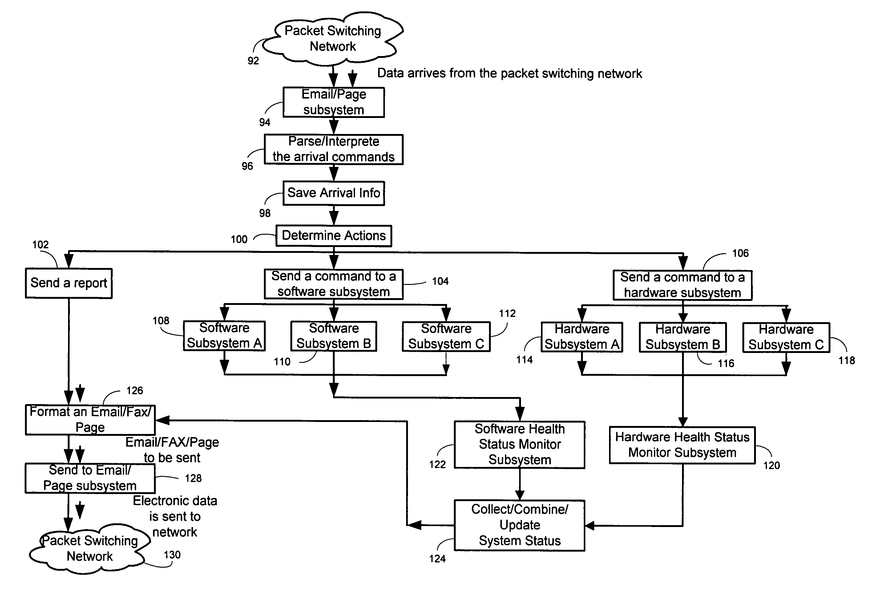
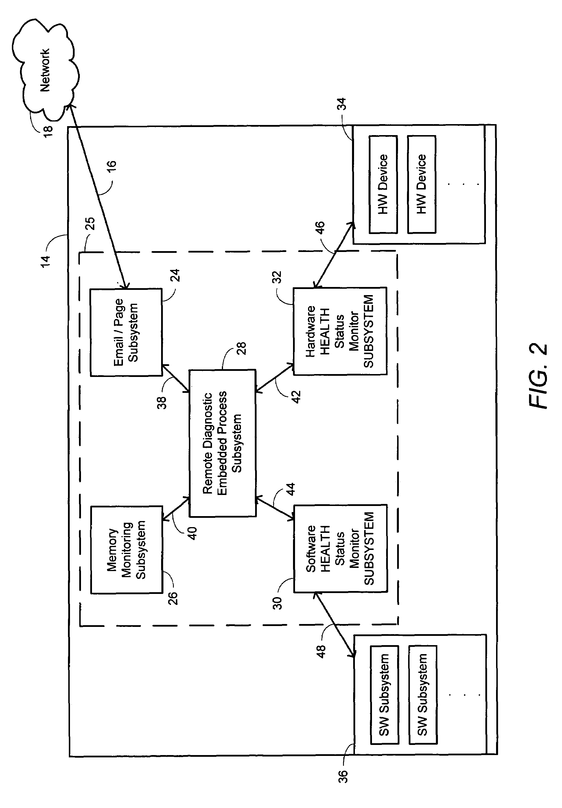
[0011]Briefly, in an embodiment of the present invention, a network device is disclosed for use in a communication system having a technical support center operated by a technical support staff, the technical support center being in communication with the network device through a packet switching network. The network device includes one or more hardware subsystems, one or more software subsystems and means for monitoring the sta

Problems solved by technology

Under such circumstances, it is common to have equipment failure, which would then require diagnostic evaluation and debugging.
This is commonly a considerably time-consuming and rigorous process.
Currently, when a component within a router fails, the router generates error messages for notification of the failure.
Among these are problems arising in the hardware and software components of various devices and communication lines and interfaces connecting the various devices of the communication system together.
When there is a hardware problem, such as the failure of a board in one of the devices due to overheating, the driver in the device detects the problem by receiving an error message from the board thereby alerting the software that is being executed in the device of the device's failure.
However, when the system fails, the valuable information regarding the reason for failure, which may be embedded in an error message in the software, may be lost, making the task of diagnosing the cause of failure more difficult and time-consuming by erasing any potential clues which might otherwise help an engineer in diagnosing the problem.
By way of execution of the software in a device, relevant information regarding the failure of the device exists but it is not necessarily communicated to the technical support staff after the device has failed.
When the device, which might be a computer or an access server (router), is powered down and then powered back on, the original problem may disappear during rebooting or the conditions, which caused the problem, may no longer exist.
Such is the case when a board malfunctions due to overheating and resumes functioning properly once it is cooled.
Similarly, an existing problem may not recur immediately after the device is rebooted and may resurface at a later time making the task of troubleshooting (or debugging) more difficult.
Currently, such information is not communicated to the technical support center and remains isolated within the device.

Method used


Image

  • Diagnostic/remote monitoring by email
  • Diagnostic/remote monitoring by email
  • Diagnostic/remote monitoring by email

Examples


Embodiment Construction

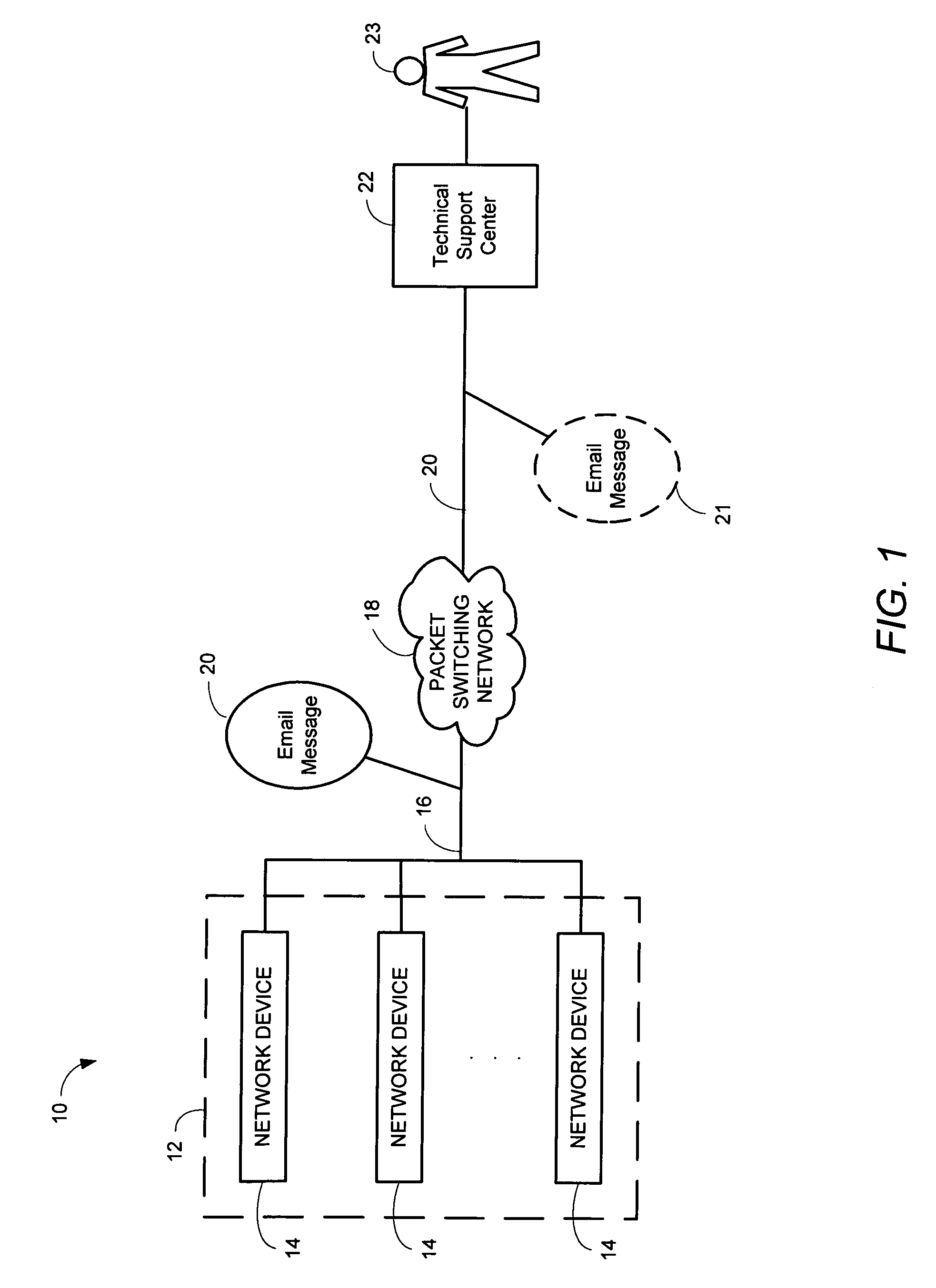
[0019]Referring now to FIG. 1, a communication system 10 is shown to include a network device assembly 12, a packet switching network 18 and a technical support center 22 for use by technical support staff 23 in accordance with an embodiment of the present invention. The network device assembly 12 comprises numerous network devices 14, which may be various types of network devices such as network access servers, routers, computer, etc. The network device assembly 12 may include a large number of network devices. A typical application includes hundreds of routers, each of which is an AS5800 model manufactured by Cisco Systems, Inc. of San Jose, Calif.

[0020]In one embodiment of the present invention, the packet switching network 18 may be an Internet Protocol (IP) network, such as the Internet. The technical support center 22 is a center equipped with computers and diagnostic equipment typically located at a laboratory site.

[0021]Each of the network devices 14 is coupled to the packet...


PUM


Abstract

A network device for use in a communication system having a technical support center operated by a technical support staff, the technical support center being in communication with the network device through a packet switching network. The network device includes one or more hardware subsystems, one or more software subsystems and means for monitoring the status of the hardware and software subsystems so that when a problem occurs with respect to one or more of the hardware and software subsystems of the network device, the network device for transmitting a first message to the technical support center to notify the technical support center of the problem, wherein the technical support staff is able to diagnose the problem without interruption to the operation of the network device.

Description

BACKGROUND OF THE INVENTION[0001]1. Field of the Invention[0002]The present invention relates generally to a method and apparatus for detecting a problem with a network device employed in a communication system and particularly to a method and apparatus for detecting a hardware or software-related problem within one or more network device among a large number of operational network devices within the communication system.[0003]2. Description of the Prior Art[0004]In modern communication systems, there may be a large number of network devices such as mail servers, routers and computers present within a system. Under such circumstances, it is common to have equipment failure, which would then require diagnostic evaluation and debugging. If the system includes hundreds of routers, such as in Cisco Systems Inc. laboratories, in order to identify the router that has failed, an engineer located at a technical support center must establish at least limited communication with every one of t...

Claims


Application Information

Patent Timeline
IPC IPC(8): G06F15/173
CPCH04M11/04
Inventor LY, JOHN DUNG-QUANG
Owner CISCO TECH INC
Learn More