Bypass discharge path for a power sourcing equipment

a technology of power sourcing equipment and bypass path, which is applied in the direction of non-electric variable control, process and machine control, instruments, etc., can solve the problems of requiring the use of a substantial transient surge suppressor or damag

Inactive Publication Date: 2007-10-09
NEVERMORE SOLUTIONS
View PDF10 Cites 220 Cited by
  • Summary
  • Abstract
  • Description
  • Claims
  • Application Information

AI Technical Summary

Benefits of technology

[0012]Accordingly, it is a principal object of the present invention to overcome the disadvantages of prior art. This is provided in the present invention by providing a bypass path to the unidirectional current flow means preventing discharge of the output capacitor. The bypass path is operated by the control circuit just before, or contemporaneously with the disabling of power to the output port. Disabling of the output port may be in response to a received command or in response to as sensed invalid DC or AC MPS.
[0016]The invention independently provides for a method for preventing an excess voltage from appearing at an output of a power over Ethernet controller, the method comprising: sensing that a powered device has been disconnected from a port; enabling a bypass path around a means for unidirectional current flow operatively connected to the port; and disconnecting power to the port responsive to the sensed disconnect, whereby the bypass path enables a discharge path for an output capacitor present across the port.

Problems solved by technology

Such an excess voltage can lead to damage or require the use of a substantial transient surge suppressor.

Method used


Image

  • Bypass discharge path for a power sourcing equipment
  • Bypass discharge path for a power sourcing equipment
  • Bypass discharge path for a power sourcing equipment

Examples


first embodiment

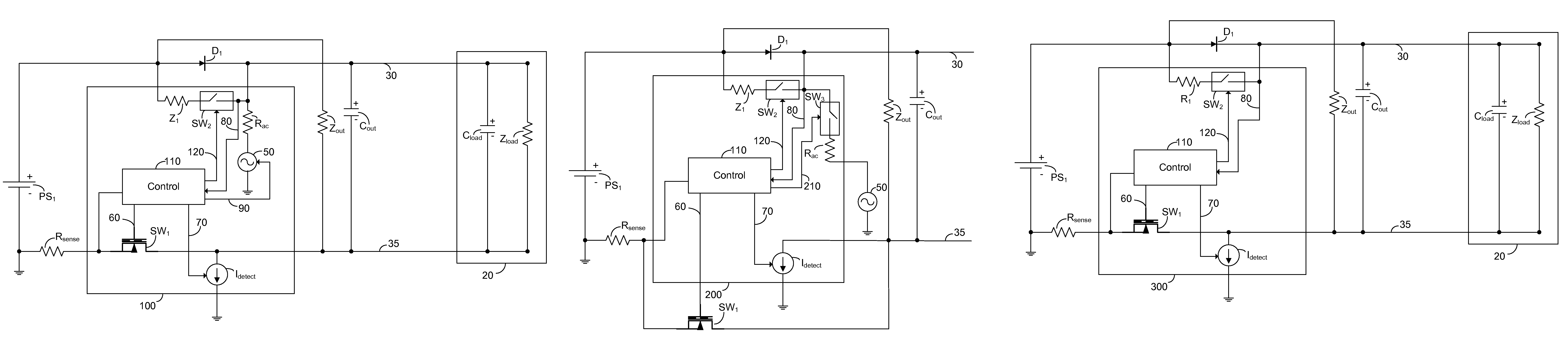
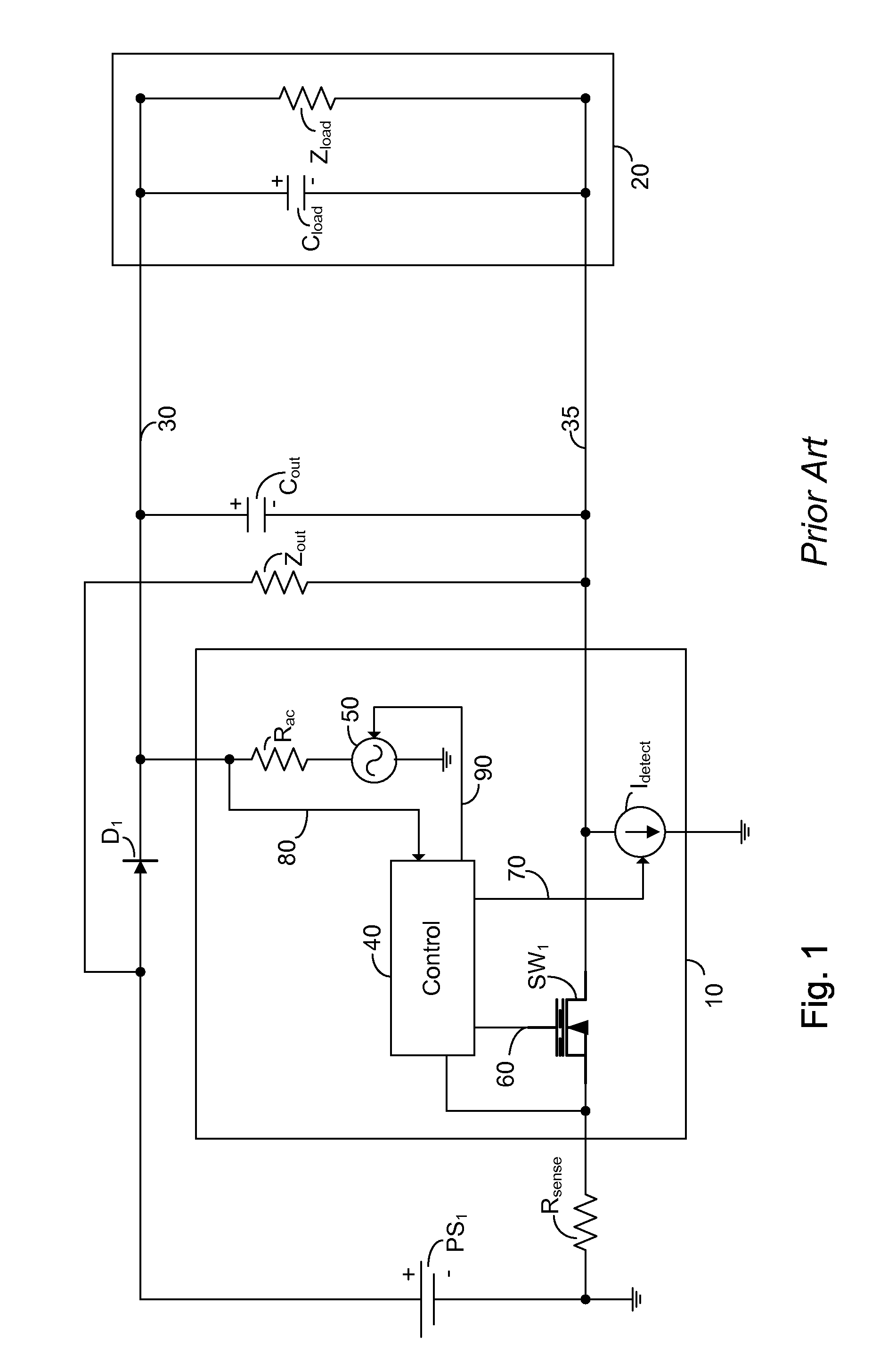
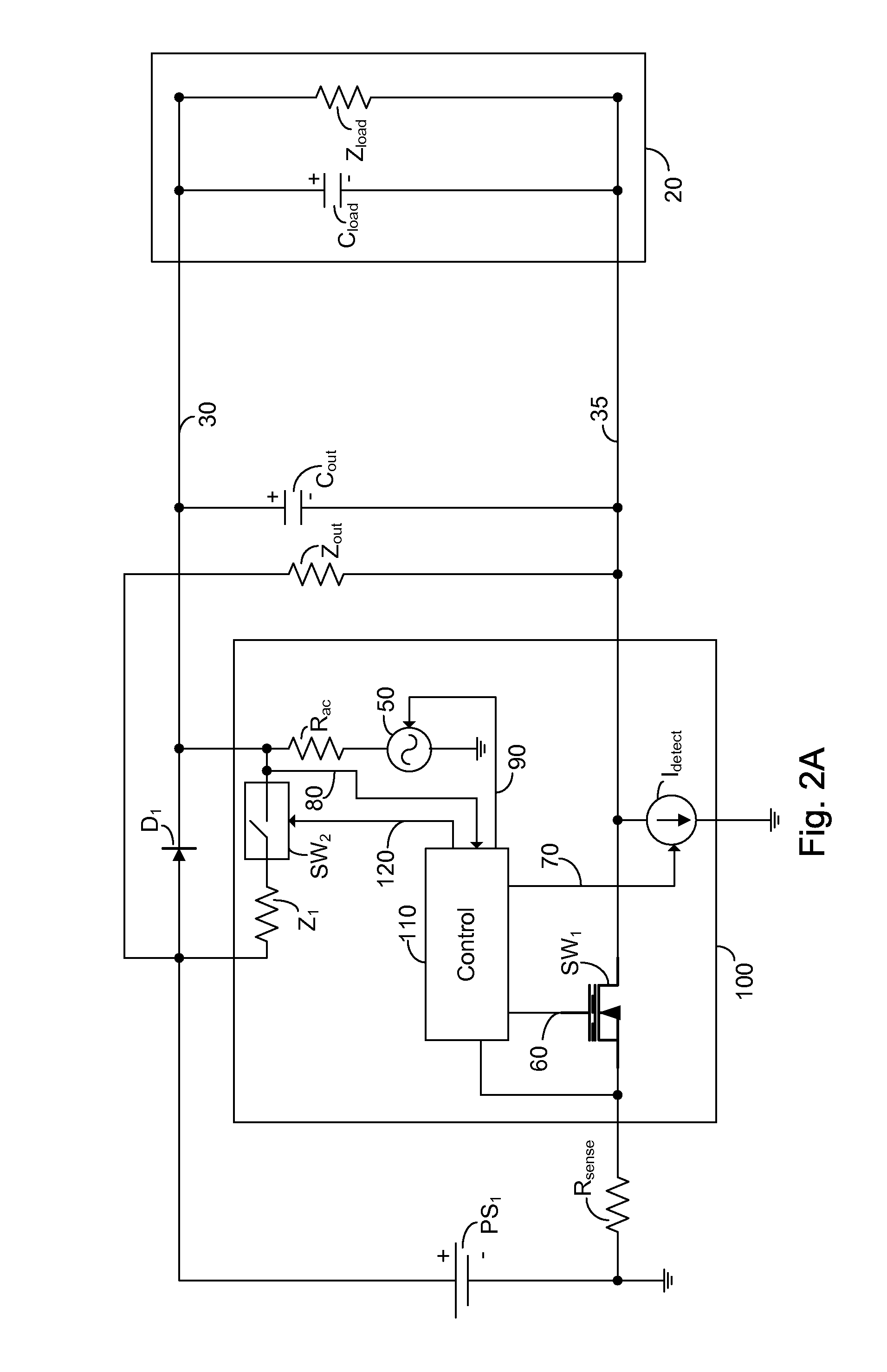
[0038]FIG. 2a is a high level schematic diagram of a power over Ethernet controller arranged to monitor an AC MPS component for disconnection of a powered device, power over Ethernet controller 100 providing a bypass path in accordance with the principle of the invention. The system of FIG. 2a comprises power over Ethernet controller 100, powered device 20, first twisted pair 30, second twisted pair 35, power source PS1, sense resistor Rsense, unidirectional current means D1, output impendence Zout and output capacitor Cout. Power over Ethernet controller 100 comprises control circuit 110, AC signal source 50, AC signal source resistance Rac electronically controlled switch SW1, detection source Idetect, control means 60, control means 70, sensing input 80, control means 90, bypass path switch SW2, bypass path impedance Z1 and bypass control means 120. Powered device 20 comprises Cload and Zload. SW1 is illustrated as a power MOSFET, however this is not meant to be limiting in any w...

second embodiment

[0045]FIG. 2b is a high level schematic diagram of a power over Ethernet controller arranged to monitor an AC MPS component for disconnection of a powered device, power over Ethernet controller 200 providing a bypass path in accordance with the principle of the invention. Power over Etherent controller 200 is illustrated with associated first twisted pair 30 and second twisted pair 35, power source PS1, sense resistor Rsense, unidirectional current means D1, output impendence Zout, output capacitor Cout, AC signal source 50 and electronically controlled switch SW1. Power over Ethernet controller 200 comprises control circuit 110, AC signal source resistance Rac, detection source Idetect, control means 60, control means 70, sensing input 80, control means 210, AC signal control switch SW3, bypass path switch SW2, bypass path impedance Z1 and bypass control means 120. SW1 is illustrated as a power MOSFET, however this is not meant to be limiting in any way. SW1 may be implemented as a...


PUM


Abstract

A method for preventing an excess voltage from appearing at an output of a power over Ethernet controller, the method comprising: sensing that a powered device has been disconnected from a port; enabling a bypass path around a means for unidirectional current flow operatively connected to the port; and disconnecting power to the port responsive to the sensed disconnect, whereby the bypass path enables a discharge path for an output capacitor present across the port. The invention also provides for a circuit having a bypass path around a means for unidirectional current flow, the bypass path being enabled by a control circuit to prevent an excess voltage from appearing at a sensing input of the control circuit. In an exemplary embodiment the bypass path is enabled approximately simultaneously with disconnecting power from the output port.

Description

BACKGROUND OF THE INVENTION[0001]The present invention relates to the field of powering ports, and more particularly to a powering circuit having a bypass path to prevent excess voltage during port disconnect.[0002]The growth of local and wide area networks based on Ethernet technology has been an important driver for cabling offices and homes with structured cabling systems having multiple twisted wire pairs. The ubiquitous local area network, and the equipment which operates thereon, has led to a situation where there is often a need to attach a network operated device for which power is to be advantageously supplied by the network over the network wiring. Supplying power over the network wiring has many advantages including, but not limited to; reduced cost of installation; centralized power and power back-up; and centralized security and management.[0003]Several patents addressed to this issue exist including: U.S. Pat. No. 6,473,608 issued to Lehr et al., whose contents are inc...

Claims


Application Information

Patent Timeline
Patent Type & Authority Patents(United States)
IPC IPC(8): G06F1/26
CPCG06F1/305
Inventor ELKAYAM, SHIMONPELEG, AMIRBARNEA, NADAVKORCHARZ, DROR
Owner NEVERMORE SOLUTIONS
Why Eureka
Try Eureka