
System and method for regenerative and antiskid braking within an electric vehicle

Inactive Publication Date: 2007-10-16
FORD GLOBAL TECH LLC
View PDF16 Cites 49 Cited by
  • Summary
  • Abstract
  • Description
  • Claims
  • Application Information

AI Technical Summary

Benefits of technology

[0008]It is a second object of the invention to provide a system and a method for regenerative and antiskid braking within a vehicle which increases fuel economy and the effective range of the vehicle by minimizing the amount of time that the regenerative braking system is disabled.
[0009]It is a third object of the invention to provide a method for controlling a regenerative braking system and an antiskid braking system within an electric vehicle which provides a more consistent brake “feel”.

Problems solved by technology

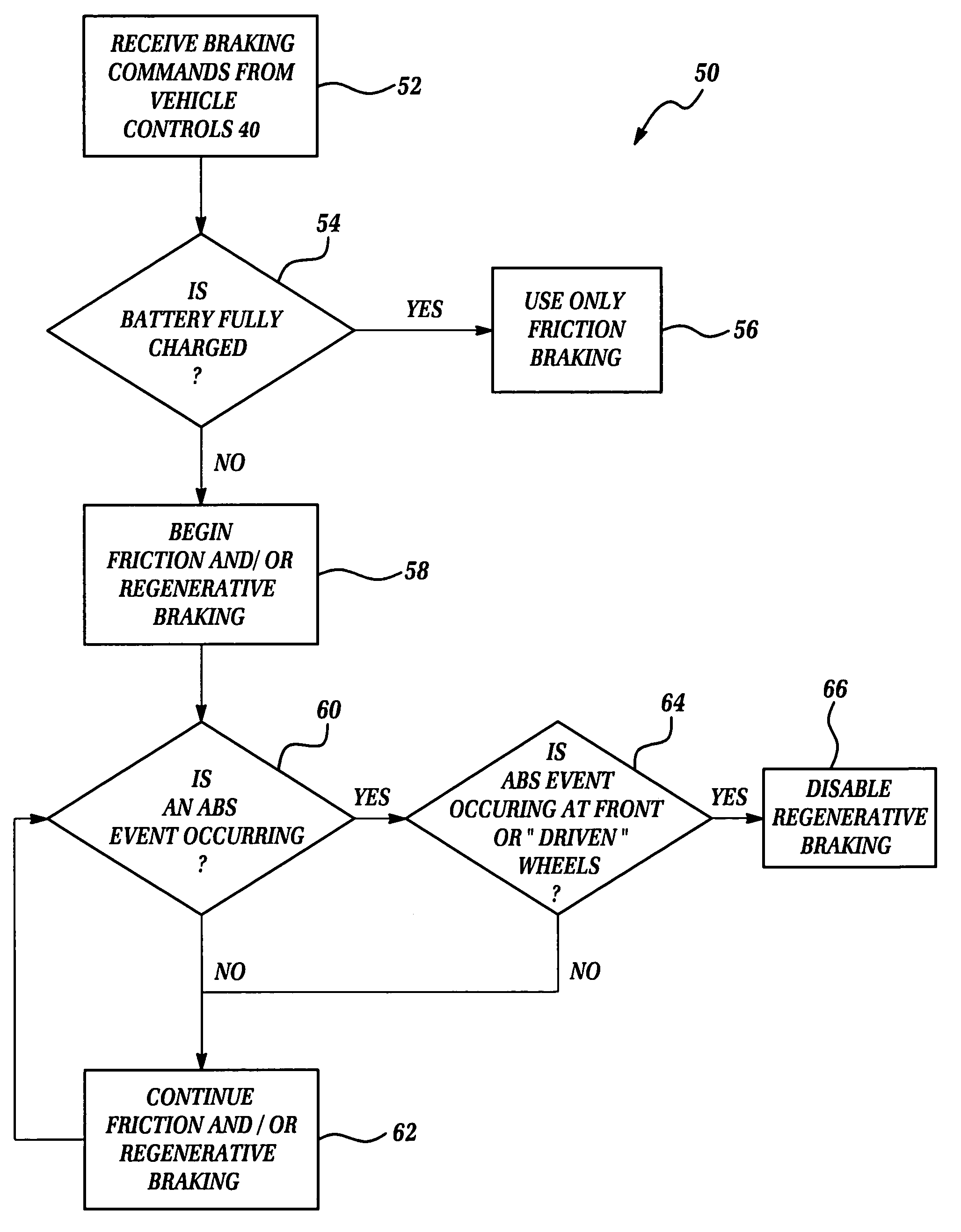
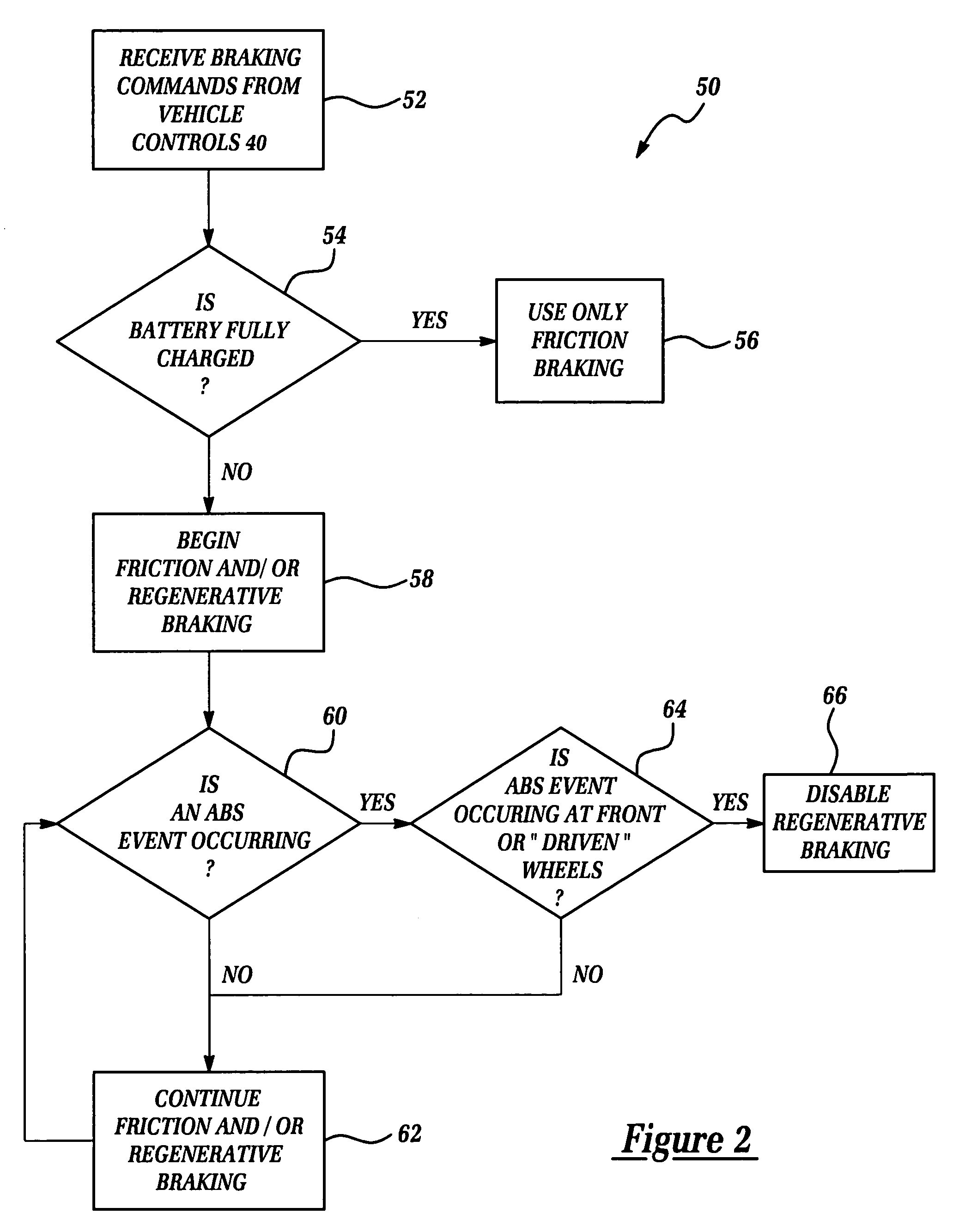
However, upon detection of an antiskid braking event, the system rapidly reduces the regenerative braking force and increases the amount of force provided by the antiskid braking system.
This reduction or elimination of the regenerative braking force during antiskid events is required due to the inability and / or difficulty of the regenerative braking system to accurately provide a modulated braking force at the same frequency as the antiskid braking system, and due the tendency of the regenerative braking system to “work against” or impair the operation of the antiskid braking system during these events.
One drawback with these prior systems is that they frequently eliminate or “shut down” the regenerative braking system upon sensing any potential antiskid event.
Thus, by disabling the regenerative braking function during these events, these prior systems unnecessarily lose the power-generating capabilities of the regenerative braking system during these events.
Furthermore, these systems also suffer from an inconsistent braking “feel”, due to the temporary power loss incurred when the regenerative torque is eliminated.

Method used


Image

  • System and method for regenerative and antiskid braking within an electric vehicle
  • System and method for regenerative and antiskid braking within an electric vehicle
  • System and method for regenerative and antiskid braking within an electric vehicle

Examples


Embodiment Construction

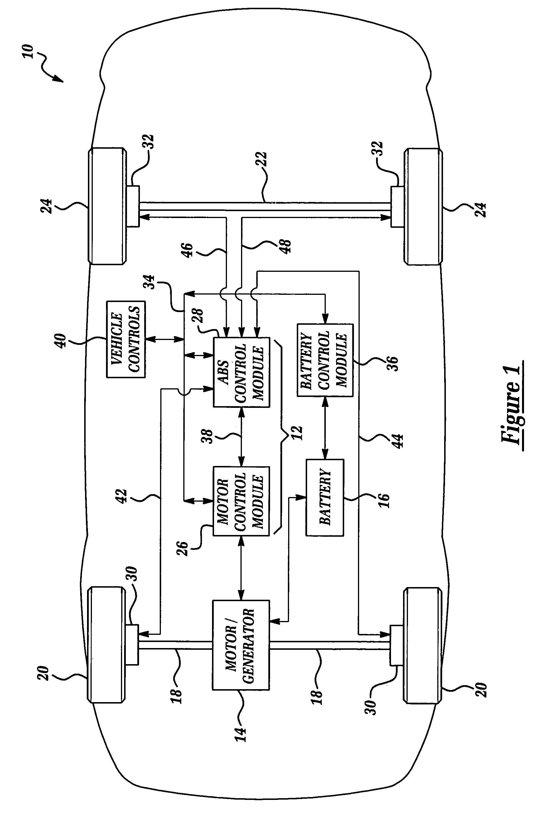
[0015]Referring now to FIG. 1, there is shown an automotive electric vehicle 10 having a braking system 12 which is made in accordance with the teachings of the preferred embodiment of the present invention. Vehicle 10 includes an electric motor / generator assembly 14, and a conventional electrical energy storage device 16 (e.g., a battery, fuel cell or other electrical energy storage device). Electrical storage device 16 receives power from and provides power to motor / generator 14. The electric motor / generator 14 is a conventional electric machine which selectively operates as an electric motor and a generator. Motor / generator 14 provides torque and power to the vehicle's front axle assembly 18 which transfers the torque to the front wheels 20, thereby rotatably driving front wheels 20. It should be appreciated that the terms “front” and “rear” are used herein for convenience purposes only (e.g., to respectively refer to the motor-driven wheels and the non-motor driven wheels), and ...


PUM


Abstract

A braking system 12 for use with an electric vehicle 10 including an electric motor / generator assembly 14, and a conventional electrical energy storage device 16. Motor / generator 14 selectively drives wheels 20 of vehicle 12. The braking system 12 includes a motor control module 26 which is communicatively coupled to motor / generator 14 and which selectively causes motor / generator 14 to provide a regenerative braking function at wheels 20 of vehicle 10. Braking system 10 further includes an antiskid braking system which selectively provides friction braking at wheels 20 and 24 of vehicle 10. The braking system 12 is effective to detect antiskid braking events at each of the wheels 20, 24, to selectively provide an antiskid braking function at each of wheels 20, 24 where the antiskid braking events are detected, and to selectively disable the regenerative braking function only when an antiskid braking event is detected at either of wheels 20.

Description

(1). FIELD OF THE INVENTION[0001]This invention relates to a system and a method for regenerative and antiskid braking within an electric or hybrid electric vehicle and more particularly, to a system and method for regenerative and antiskid braking which provides improved performance, efficiency and reliability.(2). BACKGROUND OF THE INVENTION[0002]Many electric and hybrid electric vehicles employ both a conventional antiskid braking system and a regenerative braking system. The antiskid braking system typically includes several frictional drum or disc type braking assemblies which are selectively actuated by a hydraulic system. A control system modulates the hydraulic pressure applied to the frictional braking assemblies in a manner which controls the slippage of the vehicle's wheels relative to the road surface. The regenerative braking system within these vehicles utilizes the vehicle's electric motor to provide a negative torque to the driven wheels and converts the vehicle's ki...

Claims


Application Information

Patent Timeline
IPC IPC(8): B60T8/64
CPCB60L7/18B60T1/10B60T8/00B60T8/17616B60W10/08B60W10/184B60W30/18127Y02T90/16B60W2510/244B60T2270/602
Inventor CURRAN, PATRICK JOSEPHCROMBEZ, DALE SCOTTPERACH, ASI
Owner FORD GLOBAL TECH LLC
Learn More