
Quick assembly blades for ceiling fans

Inactive Publication Date: 2007-10-16
CHIEN LUEN INDS
View PDF69 Cites 34 Cited by
  • Summary
  • Abstract
  • Description
  • Claims
  • Application Information

AI Technical Summary

Benefits of technology

[0007]The first objective of the present invention is to provide detachable blades for ceiling fans that are easy and quick to install.
[0014]A fourth embodiment has a single planar blade with an end having a slot. The mounting arm has an end with two parallel plates separated from one another by a central housing having back to back spring loaded piston rods. Passing the slotted end of the blade around the central housing so that the piston rods expand into grooves within the interior walls of the slot opening of the blade. Overhanging portions of the parallel plates further support the sides of the blade about the slot. Latch handles attached to the piston rods allow a user to manually move the piston rods against their respective springs to release the blade from the mounting arm.
[0015]A fifth embodiment has a single planar blade with an end having a slot with grooved interior walls. The mounting arm has an end with a top plate having uneven sides separated from a substantially rectangular bottom plate by a central housing having a spring loaded piston rod. The slotted end of the blade is positioned over the top plate so that the sides of the slot can abut against the bottom plate. Pulling the blade away from the mounting arm causes the piston rod to expand into a groove within the interior wall of the slot opening of the blade. The grooves and overhanging portions of the top plate and bottom plate prevents centrifugal forces caused from spinning the blade to dislodge the blade. Overhanging portions of the top and bottom plates further support the sides of the blade about the slot. A latch handle attached to the piston rod allows a user to manually move the piston rod its spring to release the blade from the mounting arm.

Problems solved by technology

Ceiling fans primarily have blades that are attached to the motor housing brackets by multiple screws and the like, Screwing the blades onto a ceiling mounted motor is not only difficult to accomplish, but results in most ceiling fans in the market place having visible screws that are unsightly.
Furthermore, the underside location of the fastener screws detract from the appearance of the ceiling fan itself.
Another problem is from the ceiling fans having to run under continuous vibration conditions where the screws can loosen causing the blades to be accidentally released and result in damages to surrounding property and people in the vicinity.
This messy cleaning with brushes causes the dirt to fall on both the cleaner and furniture and flooring below the fan.
Attempts have been made at changing the attachment methods for the blades but still fail to overcome all the problems presented above.
A still further problem of many of these detachable ceiling fan type blades is that natural centrifugal forces of the spinning fans increases the chances of dislodging the blades.

Method used


Image

  • Quick assembly blades for ceiling fans
  • Quick assembly blades for ceiling fans
  • Quick assembly blades for ceiling fans

Examples


embodiment 100

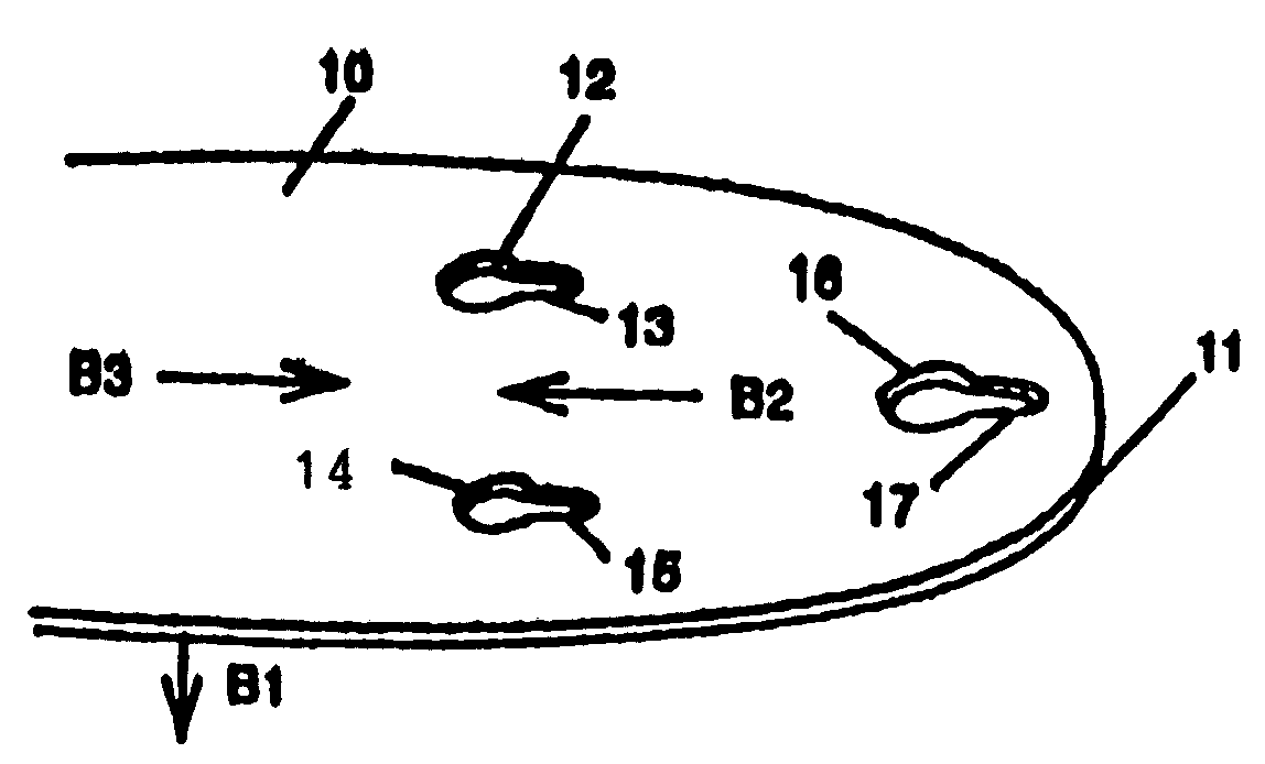
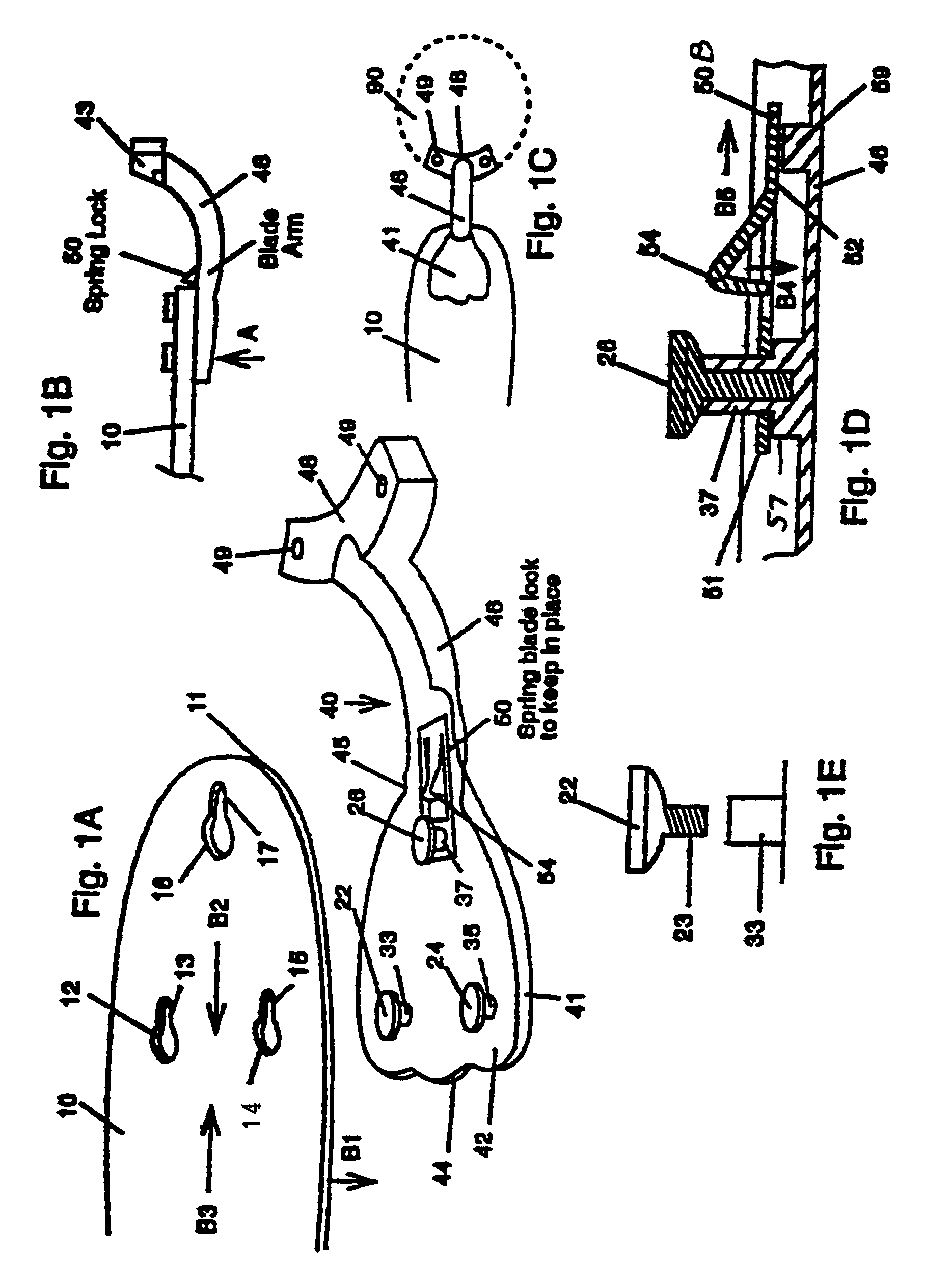
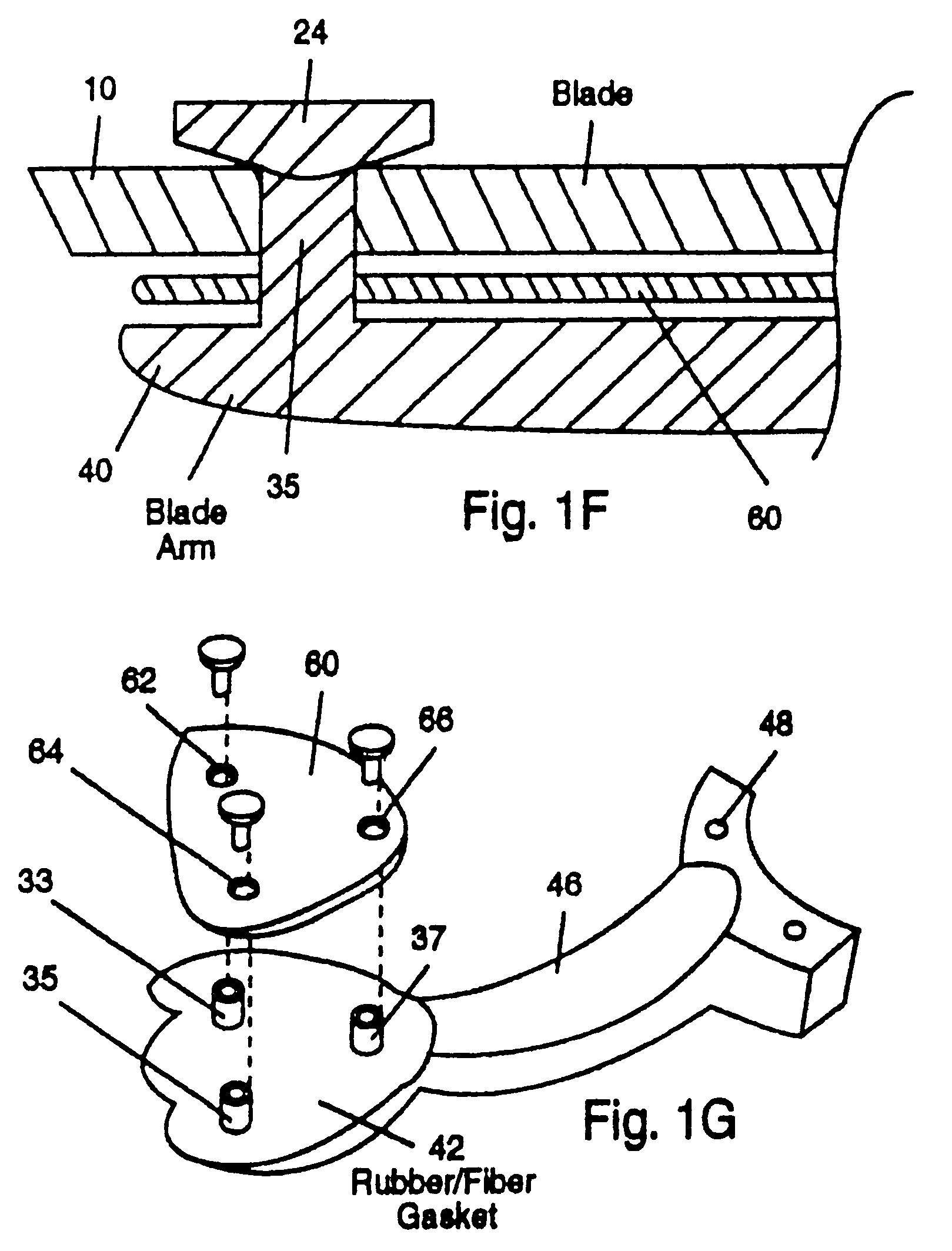
[0048]Referring to FIGS. 2A-2D, embodiment 100 includes planar shaped ceiling fan blade 110 having three keyhole slots arranged in a triangular pattern through the wide planar portion 111 of the blade 110. Each keyhole slot includes a wide diameter bases 113, 115, 117 and a narrow longitudinal portions 112, 114, 116, respectively. Mounting arm 140 includes a flat generally paddle shaped blade mounting portion 141 having an outer wider end 144 and a narrower region 145 connecting to a curved narrow connecting arm portion 146. Flat headed fasteners with stems(such as those described in the previous embodiment) 122, 124, 126 are arranged in a triangular pattern on the underside 142 of blade mounting portion 141. The other end of mounting arm 140 includes a curved ceiling fan motor mount 148 having through-holes 149 that enable fasteners such as screws(not shown) for mounting to a centrally located conventional ceiling fan(not shown). A cover cap 160 has a molded plastic base 161 with a...

embodiment 400

[0053]FIG. 5A is an exploded view of a fifth preferred embodiment 400 of the detachable blade 410 and mounting arm 440. FIG. 5B is a side view of the mounting arm 440 of FIG. 5A along G1 and the blade 410 positioned above. FIG. 5C is a front view of the mounting arm 440 of FIG. 5B along arrow G2. FIG. 5D is a top view of the blade 410 first positioned over the mounting arm 440. FIG. 5E is a top view of the blade 410 and mounting arm 440 of FIG. 5D after blade 410 is pulled in the direction of arrow H2.

[0054]Referring to FIGS. 5A-5C, mounting arm 440 includes curved narrow connecting arm portion 446 and curved ceiling fan motor mount 448 similar to those described in the previous embodiments. Arm mount 440 further includes top plate 450 with uneven sides and bottom substantially rectangular planar plate 470 which are connected to one another through a central housing 482 and 484 by screw fasteners 451. Central housing 484 has side extension portions 489 on both sides(only one is show...


PUM

PropertyMeasurementUnit
Diameteraaaaaaaaaa
Shapeaaaaaaaaaa

Abstract

Easy to attach and detach blades for overhead ceiling fans. A first version has a ceiling fan blade with keyhole slots that fit over flat topped fasteners on a mounting arm. Pulling the blade away from the arm locks the slots to the fasteners. A second version is similar to the first and has a decorative bottom cover having snappable tapered protrusions which attach through the keyholes and into mateable through-holes in the mounting arm connection. The third version has a protruding end portion of the blade that fits into a slot in the mounting arm where spring loaded pistons press into grooves in the protrusion end portion of the blade. Latching handles allow users to manually move the pistons. A fourth version has a slot in the blade which fits about a mateable housing in the mounting arm where opposing spring loaded pistons press into interior wall grooves in the slot of the blade. A fifth version has the blade with slots fit over the end of the mounting arm so that pulling the blade from the mounting arm causes spring loaded piston to interlock into a interior wall groove in the slot of the blade.

Description

[0001]This is a divisional application of Ser. No. 09 / 989,827 filed Nov. 21, 2001, now U.S. Pat. No. 6,802,694, which is a divisional application of Ser. No. 09 / 708,291 filed November 8, 2000 now U.S. Pat. No. 6,336,792 which is a divisional application of Ser. No. 09 / 200,607 filed Nov. 30, 1998 now U.S. Pat. No. 6,171,059 which is a divisional application of Ser. No. 08 / 851,501 filed May 5, 1997 now U.S. Pat. No. 6,010,306.[0002]This invention relates to ceiling fans, and in particular to easy to attach and detach blades for overhead ceiling fans.BACKGROUND AND PRIOR ART[0003]Ceiling fans primarily have blades that are attached to the motor housing brackets by multiple screws and the like, Screwing the blades onto a ceiling mounted motor is not only difficult to accomplish, but results in most ceiling fans in the market place having visible screws that are unsightly. Furthermore, the underside location of the fastener screws detract from the appearance of the ceiling fan itself. An...

Claims


Application Information

Patent Timeline
IPC IPC(8): F04D29/34
CPCF04D25/088F04D29/646Y10T29/49318Y10T29/49327Y10S416/50
Inventor BUCHER, CHARLES E.BUCHER, JOHN C.
Owner CHIEN LUEN INDS
Features
  • Generate Ideas
  • Intellectual Property
  • Life Sciences
  • Materials
  • Tech Scout
  • Unparalleled Data Quality
  • Higher Quality Content
  • 60% Fewer Hallucinations
Learn More