Mode switch control system for hybrid transmission

a control system and hybrid transmission technology, applied in the direction of electric propulsion mounting, transportation and packaging, gearing, etc., can solve the problem of lowering the quality of the mode switch operation of the hybrid transmission, and achieve the effect of lowering the quality of the mode switch operation

Inactive Publication Date: 2007-10-16
NISSAN MOTOR CO LTD
View PDF6 Cites 33 Cited by
  • Summary
  • Abstract
  • Description
  • Claims
  • Application Information

AI Technical Summary

Benefits of technology

[0003]In general, a mode switch causes a change in torque balance in a hybrid transmission. In some of the transmissions, near a switching point between a high speed mode and a low speed mode, a first torque of one of the motor / generators which is desired in the high speed mode is different from a second torque which is desired in the low speed mode, while the engine torque and the transmission output torque held substantially constant. In case the first and second torques have opposite directions, there is a polarity reversal in the associated motor / generator. In a process of the mode switch with a polarity reversal of a motor / generator, an instantaneous mode switch operation is not preferable. When a torque-transmitting mechanism for establishing the low speed mode is instantaneously disengaged during the process including the polarity reversal of the motor / generator torque, the polarity reversal of the motor / generator torque causes an undue change in the transmission output torque and a discontinuity in the gear ratio. This results in lowering the quality of the mode switch operation of the hybrid transmission.
[0004]Accordingly, it is an object of the present invention to provide a mode switch control system for a hybrid transmission operable in a high speed mode for infinitely variable high speed ratios and in a low speed mode for infinitely variable low speed ratios, which is configured to smoothly switch the transmission mode from the high speed mode to the low speed mode so as not to cause an undue change in the transmission output torque and a discontinuity in a change in the transmission gear ratio.
[0005]According to one aspect of the present invention, a mode switch control system for a hybrid transmission for a powertrain, the powertrain including an engine, a motor / generator, and an output shaft, the hybrid transmission including a stationary rotating element, and a differential unit including a plurality of rotating elements to connect the engine, the motor / generator, and the output shaft to each other, comprises a first torque-transmitting mechanism selectively engageable to connect specific two of the rotating elements to establish a high speed mode to set a speed ratio of an output speed to the output shaft to an input speed from the engine to an infinitely variable high speed ratio in which a torque of the motor / generator is needed to be a first torque to serve for torque balance in the hybrid transmission near a mode-switch speed ratio which is a boundary point between the high speed mode and a low speed mode, and disengageable to disconnect the specific two rotating elements to establish the low speed mode to set the speed ratio to an infinitely variable low speed ratio in which the torque of the motor / generator is needed to be a second torque opposite in direction to the first torque, to serve for the torque balance near the mode-switch speed ratio; an actuator to adjust a torque capacity of the first torque-transmitting mechanism; a motor / generator controller to adjust a torque of the motor / generator; and a control unit in operative communication with the actuator and the motor / generator controller, to perform the following: determining an operating condition of the hybrid transmission; issuing a command indicative of switching the transmission mode from the high speed mode to the low speed mode, in accordance with the operating condition of the hybrid transmission; and performing the following, in response to the command: reducing the torque capacity of the first torque-transmitting mechanism, to disengage the first torque-transmitting mechanism; and varying the torque of the motor / generator to the second torque, in connection with the reduction of the torque capacity of the first torque-transmitting mechanism.

Problems solved by technology

This results in lowering the quality of the mode switch operation of the hybrid transmission.

Method used


Image

  • Mode switch control system for hybrid transmission
  • Mode switch control system for hybrid transmission
  • Mode switch control system for hybrid transmission

Examples


Embodiment Construction

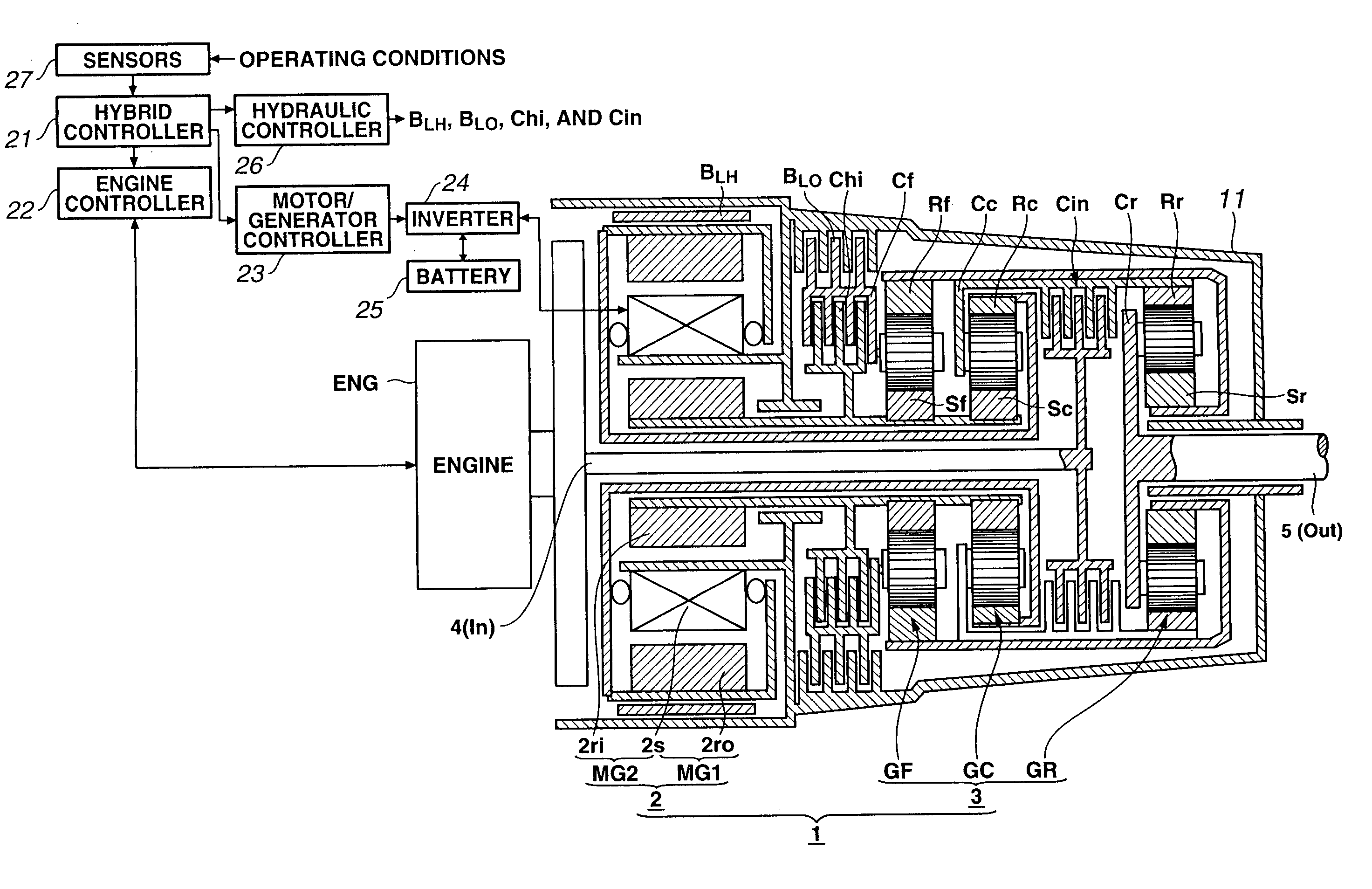
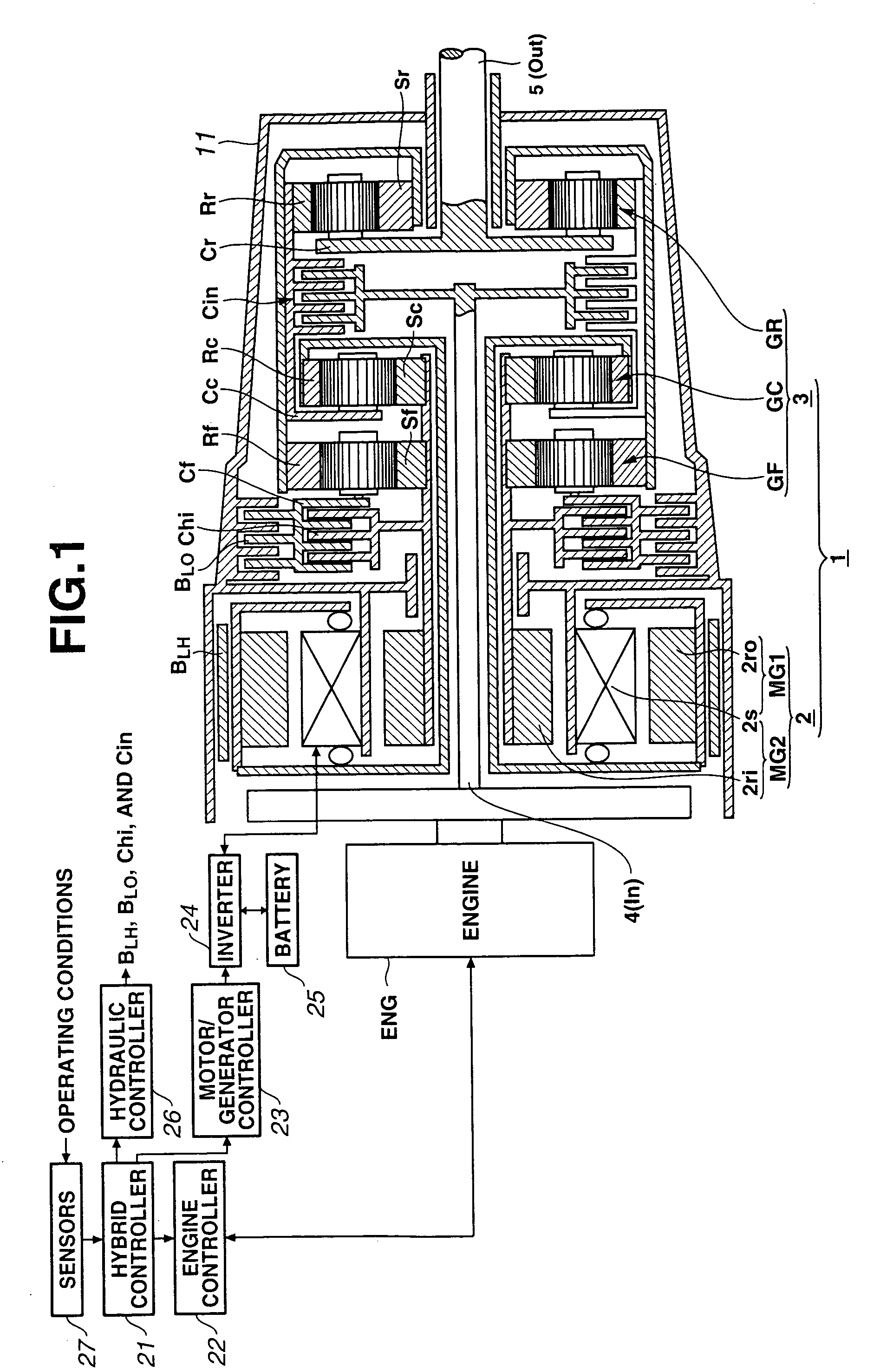
[0023]FIG. 1 is a schematic diagram depicting a hybrid transmission and a mode switch control system for the hybrid transmission in accordance with an embodiment of the present invention. Hybrid transmission 1 is configured to be mounted on automotive vehicles, especially suitable for a front engine, rear drive, vehicle. As shown in FIG. 1, hybrid transmission 1 includes a transmission housing 11 as a stationary rotating element formed into a tubular shape. Transmission housing 11 houses three planetary gearsets in a rear section located far from an engine ENG in the axial direction (on the right side in the horizontal direction in FIG. 1). More specifically, a front planetary gearset GF is mounted nearer to engine ENG. A rear planetary gearset GR is mounted farer from engine ENG. Between front planetary gearset GF and rear planetary gearset GR is disposed a central planetary gearset GC. All these planetary gearsets are mounted coaxially with transmission housing 11. In a front sect...


PUM


Abstract

A mode switch control system for a hybrid transmission for a powertrain, the powertrain including an engine, a first motor / generator, and a second motor / generator, which controls a mode switch from a high speed mode to a low speed mode. The high speed mode is established by engaging a high-mode clutch. The low speed mode is established by engaging a low-mode brake. In the mode switch, the mode switch control system reduces the torque capacity of the high-mode clutch to zero linearly in time by an open-loop control system, and varies the torque of the second motor / generator to a target torque by a feedback control system so as to adjust the gear ratio to a target gear ratio, while the mode switch control system holds substantially constant the input torque from the engine, and the torque of the first motor / generator, to hold substantially constant the output torque.

Description

BACKGROUND OF THE INVENTION[0001]The present invention relates generally to mode switch control systems for hybrid transmissions operable in a plurality of transmission modes, and more particularly to a mode switch control system for a hybrid transmission operable in a high speed mode for infinitely variable high speed ratios and in a low speed mode for infinitely variable low speed ratios, which is configured to smoothly switch the transmission mode from the high speed mode to the low speed mode so as not to cause an undue change in the transmission output torque and a discontinuity in a change in the transmission gear ratio.[0002]In recent years, there have been disclosed various hybrid transmissions. One such hybrid transmission includes a differential unit interconnecting an engine, an output shaft, and motor / generators. The differential unit includes a plurality of rotating elements, three or more of which are each configured to be connected to an associated one of the engine, ...

Claims


Application Information

Patent Timeline
Patent Type & Authority Patents(United States)
IPC IPC(8): B60W10/08B60K1/02B60W20/00B60K6/445B60L50/16B60W10/02B60W10/04B60W10/10F16H3/66F16H3/72F16H59/14F16H59/38F16H61/04F16H63/50
CPCB60K6/445B60K6/48B60W10/02B60W10/08F16H3/728B60K6/365B60K1/02Y10T477/23B60W20/00B60W2710/027F16H2037/102F16H2037/104F16H2037/106F16H2200/0039F16H2200/201Y02T10/6221Y02T10/6239Y10T477/24Y02T10/62B60W10/18B60W10/11B60W20/30
Inventor OSHIDARI, TOSHIKAZU
Owner NISSAN MOTOR CO LTD
Why Eureka
Try Eureka