System and method for monitoring a well

a well and system technology, applied in the field of fiber optic sensing technologies, can solve the problems of reducing affecting the accuracy of electronic sensors, and difficulty in powering electronic sensors electrically

Active Publication Date: 2007-10-16
BAKER HUGHES INC
View PDF36 Cites 20 Cited by
  • Summary
  • Abstract
  • Description
  • Claims
  • Application Information

AI Technical Summary

Problems solved by technology

For systems that require a string of electronic sensors over a long distance, e.g., twenty to thirty kilometers or longer, powering the electronic sensors becomes difficult.
Powering electronic sensors electrically has been a problem in the petroleum and gas industry.
However, electric wires spanning such long distances create too much interference and noise, thereby reducing the accuracy of the electronic sensors.
As discussed in greater detail herein, the sensing length LS is a simple function of L, but L also affects v, R, and f. Increasing the sensing length LS by making L arbitrarily large consequently reduces the wavelength sweep range R and increases the data acquisition frequency f to impractical values.
Similarly, the wavelength sweep range R can be restored by increasing N, but this increase comes at the expense of the size of the data set required and the amount of time required for FFT computation.
Maximizing the sensing length while maintaining speed and efficiency is a difficult challenge in the successful construction of an OFDR.
Given these challenges, a typical OFDR system is currently limited to a sensing length of about 100 meters.

Method used


Image

  • System and method for monitoring a well
  • System and method for monitoring a well
  • System and method for monitoring a well

Examples


Embodiment Construction

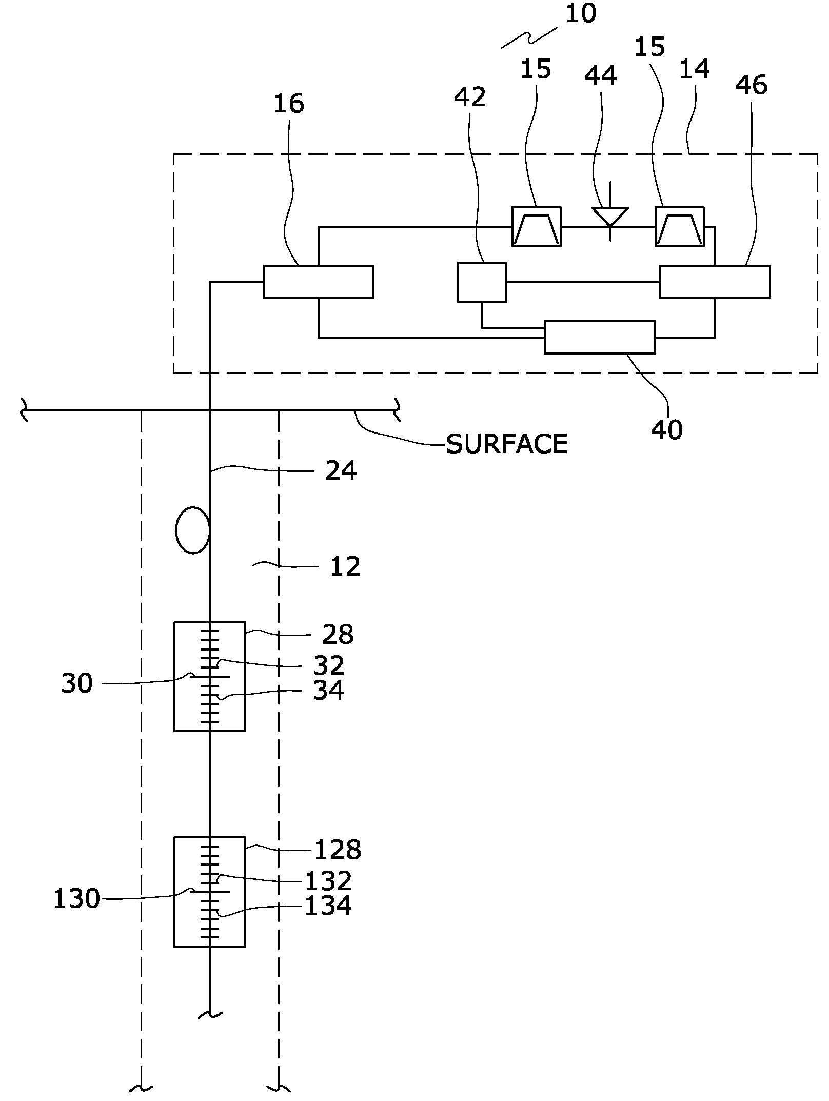
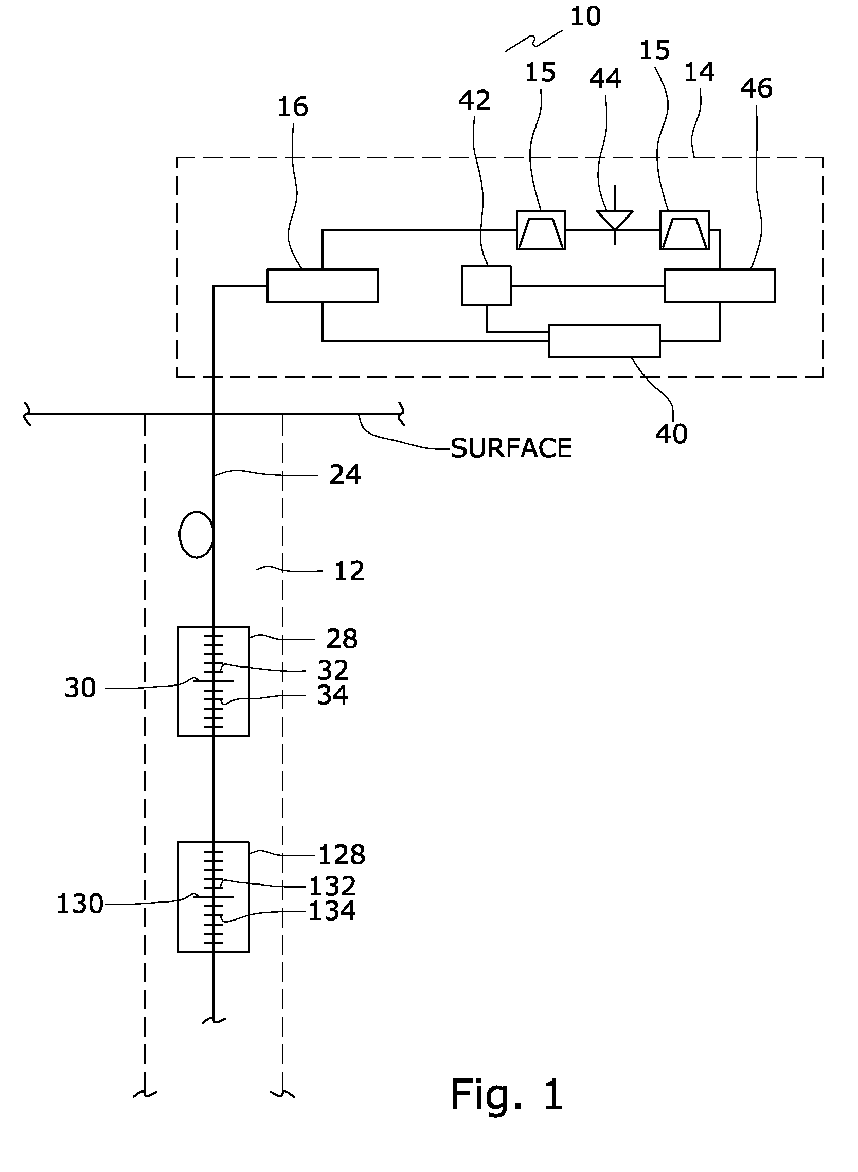
[0025]The operational properties of an OFDR are governed by the wavenumber spacing, v, the wavelength sweep range, R, the data acquisition frequency, f, and the sensing fiber length, LS. Each of these parameters is described by the following equations:

[0026]v=12⁢nLEq.⁢1

where n is the refractive index of the fiber, and L is the length of a reference interferometer;

[0027]R=λO⁡(1-λO⁢N⁢⁢ν)(1+λO⁢N⁢⁢ν)Eq.⁢2

where λ0 is the initial wavelength of the wavelength sweep, and N is the number of data points acquired during a measurement;

[0028]f=N⁢⁢v.REq.⁢3

where {dot over (v)} is the laser wavelength sweep rate; and

[0029]LS=L4.Eq.⁢4

N can be further described by the following equation:

N=2p  Eq. 5

where p is a power of two for facilitating the use of fast Fourier transforms in the processing of the signal data.

[0030]The sensing length LS is a simple function of L, but L also effects v, R, and f. Achieving a long sensing length LS by making L arbitrarily large reduces the wavelength sweep range R and ...


PUM


Abstract

An optical fiber extends down hole from an OFDR. A first set of sensors with a centrally-located reference reflector is disposed over a first fiber length, and a second set of sensors with a centrally-located reference reflector is disposed over a second fiber length. The sensors of the first and second sensing lengths are positioned at slightly offset positions from the reference reflectors so as to interleave the reflected signals. Additional sensing lengths may be similarly interleaved. The system is used by sending an optical signal along the optical fiber, detecting a reflected optical signal, separating the optical signal into component signals, and extrapolating a well condition therefrom. Another method includes creating a low frequency signal component in a reflected optical signal by placing at least one sensor beyond a Nyquist sampling distance limit, detecting the low frequency signal component, and extrapolating a well condition therefrom.

Description

BACKGROUND[0001]The invention relates generally to fiber optic sensing technologies. In particular, fiber optic sensors are used to detect conditions within a well.[0002]Available electronic sensors measure a variety of values, such as, pH, color, temperature, or pressure, to name a few. For systems that require a string of electronic sensors over a long distance, e.g., twenty to thirty kilometers or longer, powering the electronic sensors becomes difficult. Conventionally, the powering of electronic sensors requires running electrical wire from a power source to each of the electronic sensors. Powering electronic sensors electrically has been a problem in the petroleum and gas industry. However, electric wires spanning such long distances create too much interference and noise, thereby reducing the accuracy of the electronic sensors.[0003]Optical fibers have become the communication medium of choice for long distance communication due to their excellent light transmission character...

Claims


Application Information

Patent Timeline
Patent Type & Authority Patents(United States)
IPC IPC(8): G01J1/04G01B9/10G01J1/42G01J5/08
CPCE21B47/065G01D5/35303G01M11/3172G01K11/3206G01D5/35383E21B47/07G01V1/226E21B47/06G01D5/353G01K11/32
Inventor CHILDERS, BROOKS
Owner BAKER HUGHES INC
Why Eureka
Try Eureka