Battery controller and method for controlling a battery

a battery controller and battery technology, applied in the direction of transportation and packaging, battery emergency power supply arrangements, etc., can solve the problems of inability to transfer, inability to implement, and difficulty in implementing bypass circuits, etc., to achieve more energy efficiency, less cost, and the effect of saving resources

Active Publication Date: 2007-10-16
ELECTROVAYA
View PDF17 Cites 188 Cited by
  • Summary
  • Abstract
  • Description
  • Claims
  • Application Information

AI Technical Summary

Benefits of technology

[0022]A further advantage of the present invention is that in some preferred embodiments, the batteries are arranged such that the maximum nominal voltage across any battery and therefore across any DC to DC converter is preferably in the range of 5 volts to 30 volts, more preferably in the range of 10 volts to 25 volts and still more preferably in the range of 15 volts to 22 volts.
[0023]Consider a battery-powered system where the total number of batteries is represented by N, and if the total expected voltage during nominal discharge for the battery system is represented by the Vtotal, and each battery contributes approximately an equal share of the total power. In this preferred embodiment, the voltage of any one DC to DC converter is approximately Vtotal / N. preferably, this Vtotal / N value is less than 30 volts so that low-voltage, low-cost DC to DC converters can be used. In this way, while a larger number of converters may be required in order to implement the battery controller, the converters can be used in the lower voltage range, which tends to be more economical and often more energy efficient. Therefore, even though a larger number of DC to DC converters may be required, the total cost may not be significantly greater than a single converter. This cost benefit is especially likely if the rated voltage of the DC to DC converters is in the preferred ranges set forth above.

Problems solved by technology

Furthermore, as is known to persons skilled in the art, if one of the batteries 6 fails, then it is not possible to transfer any current through the failed battery with the potential result that all batteries connected in series may fail if a single battery in the series fails.
However, bypass circuits can be expensive and difficult to implement and may not be tested for a number of years or until its associated battery 6 fails.
This infrequent testing means that the circuit may not be operating at a time of emergency.
However, a system such as this, which has a centralized discharger and charger, suffers from the disadvantage that it is difficult or impossible to individually control the charging or discharging of each cell.
Furthermore, having centralized control leaves the entire system open to failure should a single cell fail.
In general, it is not possible to have current pass through a battery or cell which has failed.
If a single battery of Choy's system fails, then the entire Choy system will fail, generally requiring replacement or other service.
Each battery monitoring module will monitor a number of batteries and the current carrying wire between them, so that incipient problems may be detected before failure or significant damage occurs.
However, Nor also fails to disclosure monitoring each battery individually as opposed to a number of batteries collectively.
Furthermore, Nor fails to disclose a suitable means to deal with a failure which may be detected because Nor's battery monitoring system treats two whole sets of batteries and it's connecting circuitry as a single unified entity.
It is noted that Dickman et al. does not disclose the use of any sort of fuel-less battery, as the fuel stacks of Dickman et al. utilize hydrogen gas as a fuel.
It is further noted that Dickman et al. does not disclose the use of any sort of rechargeable battery, as the fuel stacks of Dickman et al. utilize a continuing hydrogen stream to generate its electrical power.
(See DEFINITIONS section below for definitions of “fuel-less battery” and “rechargeable battery.”) Also, because the fuel cell stacks of Dickman et al. uses a continuous stream of hydrogen gas for fuel, they do not have energy capacities the way that fuel-less batteries do.

Method used


Image

  • Battery controller and method for controlling a battery
  • Battery controller and method for controlling a battery
  • Battery controller and method for controlling a battery

Examples


Embodiment Construction

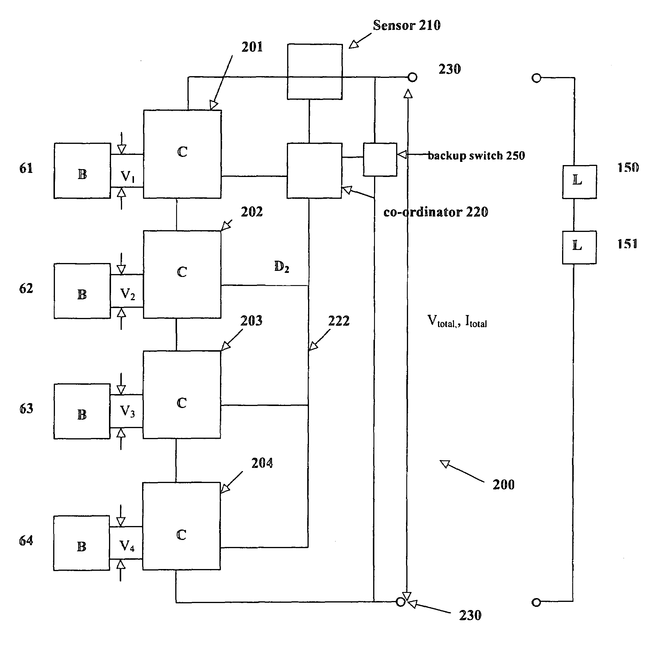
[0036]Battery controller apparatus 200, an embodiment of the present invention, is shown in FIG. 2 and will now be discussed. Apparatus 200 is designed to charge, recharge and discharge several batteries B (individually identified by reference numerals 61 to 64). Apparatus 200 further includes several DC to DC converters, shown generally by the letter C (identified individually by reference numerals 201, 202, 203 and 204). As illustrated in FIG. 2, the DC to DC converters are connected to each other in series. Each DC to DC converter C is also respectively electrically connected to a battery B selected from the set of batteries. In preferred embodiment 200, the batteries B are not electrically connected (or necessarily connectable) to each other. In alternative embodiments, there may be various series and / or parallel connections among some or all of the batteries. A potential drawback of these alternative embodiments is that failure of one or more of the connected batteries will ten...


PUM


Abstract

A battery controller for charging and discharging a plurality of batteries is disclosed. The battery controller has a plurality of direct current to direct current (DC to DC) converters connected to each other in series. Each battery of a plurality of batteries is electrically connectable to a respective DC to DC converter. A co-ordinator connected to each of the plurality of DC to DC converters controls charging and discharging of the battery electrically connected to the respective converter. The co-ordinator can also control charging and discharging of any one of the batteries to ensure that the battery retains sufficient electrical capacity, and, to increase the longevity of the respective batteries. Because each battery is electrically connected to a respective DC to DC converter, the energy from one battery can be used to charge another battery in order to monitor battery characteristics including energy capacity of each battery. Each of the DC to DC converters is selected to operate preferably below 30 volts while the total voltage of the entire battery system can be much more than 30 volts depending on the number of DC to DC converters placed in series.

Description

FIELD OF THE INVENTION[0001]This invention relates to battery controllers and methods for controlling batteries. More particularly, the present invention relates to battery controllers used to control batteries and / or power converters connected in series to provide power to a load.DESCRIPTION OF THE RELATED ART[0002]There is a growing trend for use of batteries, such as lithium ion batteries and lead acid batteries, to power various devices, as diverse as electric cars, computers and cameras. There is also a growing trend to use batteries as an alternate or emergency power source, such as for telephone systems, cable systems and other forms of communication systems or computer systems. The use of batteries helps ensure that a system will survive power failures without interruption or damage to the underlying system, or, loss of data or communication. This is particularly important for emergency communication which is essential during power failures. In order to provide current and v...

Claims


Application Information

Patent Timeline
Patent Type & Authority Patents(United States)
IPC IPC(8): H02J1/00H02J3/00H02J7/00H02J9/00
CPCH02J7/0018Y02T10/70
Inventor JACOBS, JAMES K.
Owner ELECTROVAYA
Why Eureka
Try Eureka