
Dual mode ceramic filter

a ceramic filter and dual-mode technology, applied in the direction of waveguide type devices, resonators, basic electric elements, etc., can solve the problems of difficult manufacturing of existing dual-mode resonators, inability to meet the needs of certain applications, and large bulky resonators that use hybrid modes, etc., to achieve the effect of increasing the q-valu

Active Publication Date: 2007-10-16
INTEL CORP
View PDF19 Cites 2 Cited by
  • Summary
  • Abstract
  • Description
  • Claims
  • Application Information

AI Technical Summary

Benefits of technology

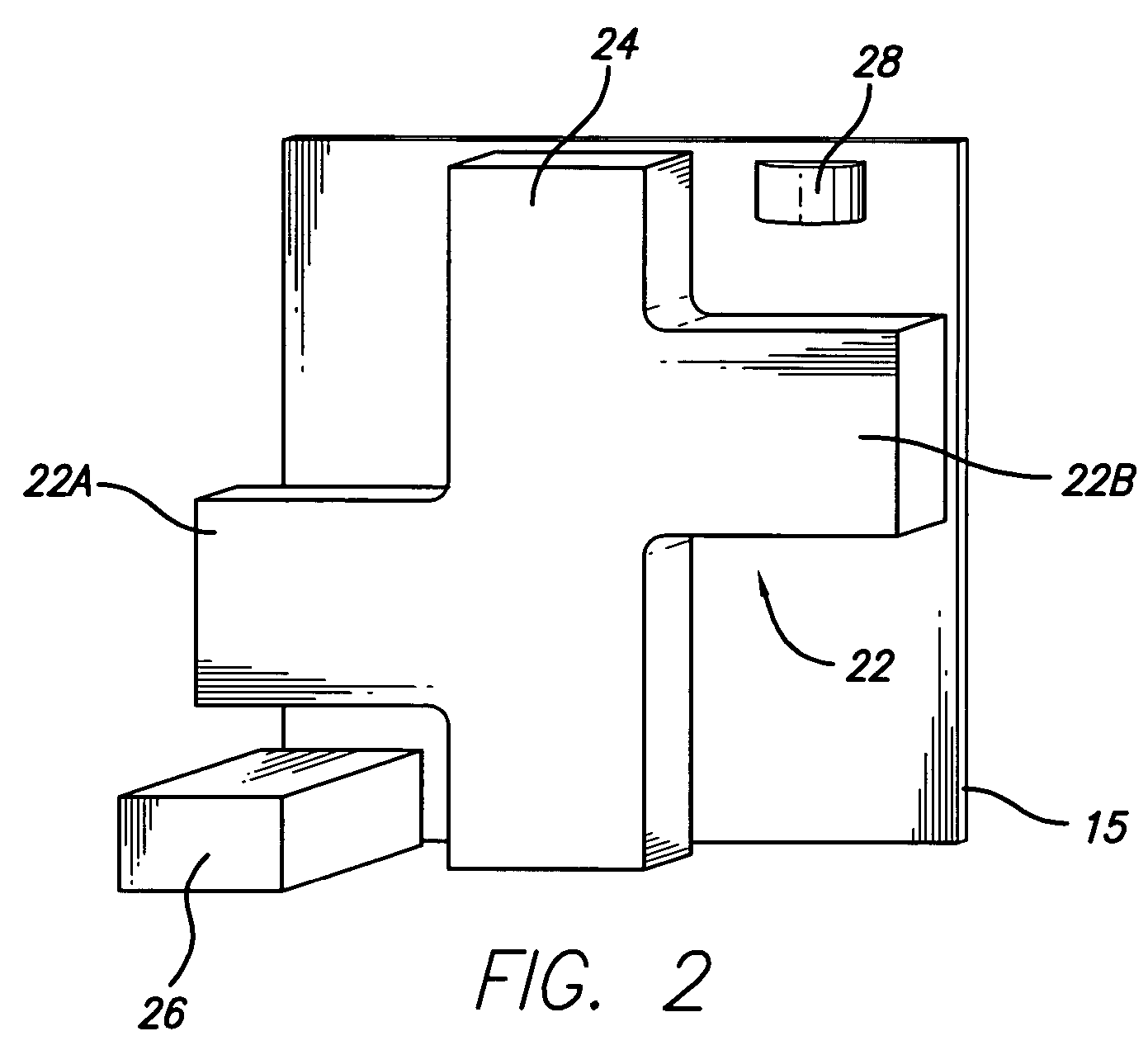
The present invention provides filters with improved coupling between a TM dual-mode resonator and an input conductive member. The filters have a cavity with an TM dual-mode resonator positioned inside it. The TM dual-mode resonator has first and second modes and a dielectric resonator body with a central portion and a plurality of arms extending outwardly from it. The input conductive member is positioned proximate to the TM dual-mode resonator for coupling between them. The filters can also have a cross-coupling member positioned in the cavity for coupling between resonator modes. The technical effects of the invention include improved coupling, fine-tuning, and reduced interference between modes.

Problems solved by technology

However, many existing dual-mode resonators are difficult to manufacture due to the shape of the resonator structure.
Other existing resonators that use hybrid modes, are too large and bulky for certain applications.

Method used


Image

  • Dual mode ceramic filter
  • Dual mode ceramic filter
  • Dual mode ceramic filter

Examples


Embodiment Construction

[0052]The present invention provides a structure for smaller base station filters. Specific embodiments and various features and aspects of the invention are described below.

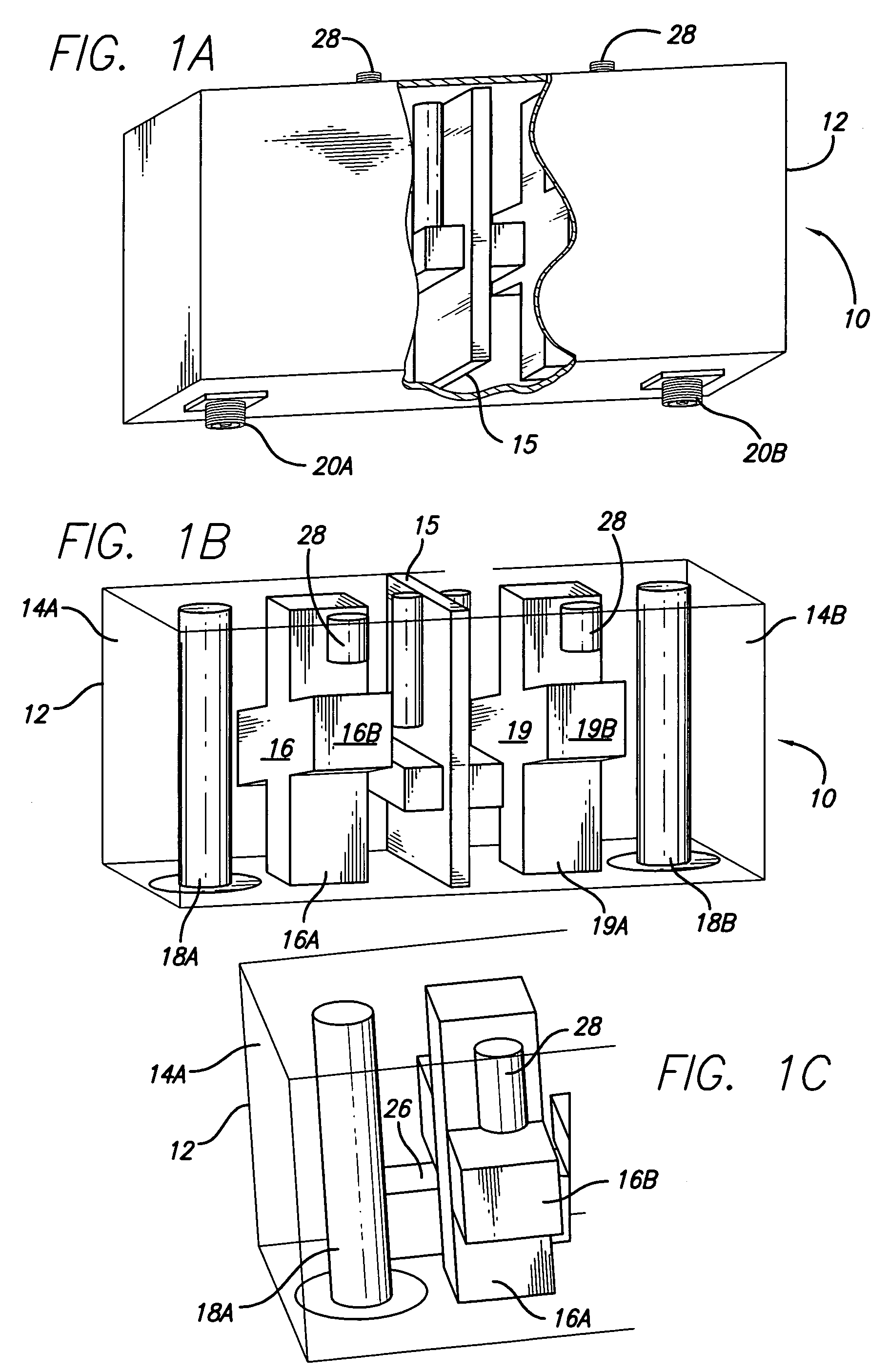
[0053]FIG. 1A is a partially broken-away perspective view of a filter 10 having a rectangular-shaped metal case 12, according to an embodiment of the present invention. FIG. 1B shows a perspective view of the interior of the filter of 10FIG. 1A, providing two cavities (i.e., 14A, 14B) separated by a wall 15, wherein each cavity houses a transverse magnetic (TM) dual mode resonator. A first TM dual mode resonator 16 is formed by resonator members 16A, 16B crossing each other at a mid-point to form a “cross” or “X” in cavity 14A. A second TM dual mode resonator 18 is formed by resonator members 19A, 19B crossing each other at a mid-point to form as a “cross” or “X” in cavity 14B. The filter case 12 further houses input pins (i.e., 18A, 18B) coupled to coaxial connectors (i.e., 20A, 20B). In this structure, there i...


PUM


Abstract

A dual mode ceramic filter has an enclosure with two cavities separated by a wall, and two TM dual-mode resonators, each TM dual-mode resonator positioned in a corresponding cavity. Each TM dual-mode resonator has first and second modes, and a body having a central portion with a plurality of arms extending outwardly from the central portion. The filter also has two input conductive members, each input conductive members positioned in a corresponding cavity. Each input conductive member is disposed proximate a corresponding TM dual-mode resonator for coupling between the input conductive member and the TM dual-mode resonator.

Description

RELATED APPLICATION INFORMATION[0001]The present application claims priority under 35 USC 119(e) of provisional patent application Ser. No. 60 / 651,182, filed on Feb. 9, 2005, incorporated herein by reference in its entirety.FIELD OF THE INVENTION[0002]The present invention is directed to filters for wireless communications systems, and in particular, wireless base station filters.BACKGROUND OF THE INVENTION[0003]A wireless telecommunication system typically includes a plurality of base stations connected to a communication network. Each base station includes radio transceivers associated with a transmission tower. A typical base station includes one or more filters for processing IF signals. One such filter is known as a microwave cavity filter which includes resonators formed in cavities in order to provide a desired frequency response when signals are input to the filter.[0004]One type of cavity filter design employs dual-mode resonators utilized in the cavity filters, providing d...

Claims


Application Information

Patent Timeline
Patent Type & Authority Patents(United States)
IPC IPC(8): H01P7/10H01P1/20
CPCH01P7/105H01P1/2086
Inventor ANDREASSON, KRISTERPOSHMAN, GORAN
Owner INTEL CORP
Learn More