A micromechanical resonator

A micromechanical resonator and resonator technology, applied in the field of resonators, can solve the problems of unpredictable and quantified changes in package stress, and achieve the effects of reducing energy loss, impact and energy loss.

Active Publication Date: 2021-11-02
武汉敏声新技术有限公司
View PDF5 Cites 0 Cited by
  • Summary
  • Abstract
  • Description
  • Claims
  • Application Information

AI Technical Summary

Problems solved by technology

Due to the complexity, diversification and unpredictability of the working environment of the resonator, the change of the package stress is almost impossible to predict and quantify, so there is almost no suitable technical solution to compensate and correct the package stress and the change of the package stress

Method used


Image

  • A micromechanical resonator
  • A micromechanical resonator
  • A micromechanical resonator

Examples


Embodiment 1

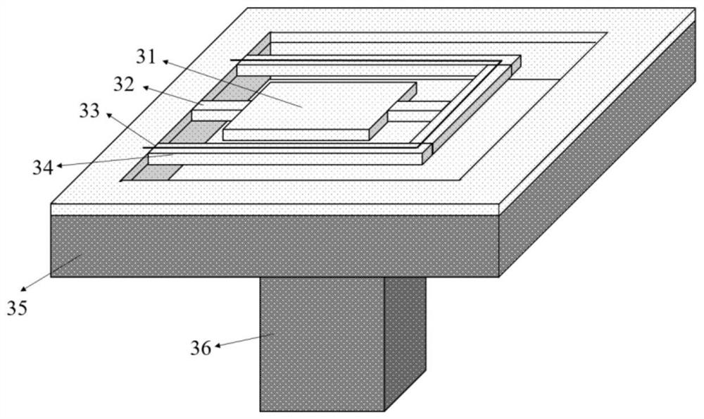
[0050] Figure 3-1 The structure of the resonator prepared in this embodiment is shown.

[0051] A micromechanical resonator comprising a substrate silicon chip 35 with a central prism structure 36, a resonator structure and a vacuum package structure,

[0052] in:

[0053] (1) A cavity is provided on the top surface of the substrate silicon wafer 35;

[0054] (2) The resonator structure includes a resonant vibrator 31, a support beam 32, an isolation frame 34 and a heating resistance wire 33; the resonant vibrator 31 is a rectangular plate structure, suspended in the cavity, and connected to the lining by two straight beam support beams 32 One side of the bottom silicon chip 35 and the "U"-shaped isolation frame 34, the support beam 32 is located at the vibration node of the resonator 31; the isolation frame 34 is connected to the inner wall side of the substrate silicon chip 35; the heating resistance wire 33 is located on the upper surface of the isolation frame 34 ;

...

Embodiment 2

[0069] Figure 3-2 The structure of the resonator prepared in this embodiment is shown.

[0070] The difference with Example 1 is:

[0071] One end of the resonant oscillator 31 in Embodiment 1 is connected to the isolation frame 34 through the support beam 32, and the other end is directly connected to the substrate silicon wafer 35 through the support beam 32; in this embodiment, the isolation frame 34 is a rectangular frame, and the resonant oscillator 31 is two Both ends are connected to the isolation frame 34 through the support beam 32.

[0072] Figure 5-2 The structural cross-sectional schematic diagram of the micromechanical resonator prepared for this embodiment, the specific manufacturing steps are as follows:

[0073] (1) Provide an SOI substrate with a cavity; this layer is composed of substrate silicon wafer 501, buried oxide layer silicon oxide 502 and resonant oscillator structure silicon layer 503 in sequence from bottom to top;

[0074] (2) deposit a bott...

Embodiment 3

[0079] Figure 3-3 The structure of the resonator prepared in this embodiment is shown.

[0080] The difference with Example 1 is:

[0081]The isolation frame 34 in Embodiment 1 is a U-shaped beam; while the isolation frame 34 in this embodiment is a snake-shaped folded beam.

[0082] Figure 5-3 The structural cross-sectional schematic diagram of the micromechanical resonator prepared for this embodiment, the specific manufacturing steps are as follows:

[0083] (1) Provide a substrate silicon wafer (SOI) with a cavity; this layer is composed of substrate silicon wafer 501, buried oxide layer silicon oxide 502 and resonator structure silicon layer 503 from bottom to top; (2) in SOI Deposit the bottom electrode layer 504 on the upper surface of the device layer, then prepare the piezoelectric film layer 505, and then prepare the top electrode layer 506 on the piezoelectric film 505;

[0084] (3) Deposit a sacrificial layer 515, which is made of silicon oxide, etch to make ...


PUM


Abstract

The invention discloses a micromechanical resonator. By optimizing the design of the geometric dimensions of the micromechanical resonator, the mechanical vibration at the boundary between the resonator of the micromechanical resonator and the support beam is reduced, thereby reducing the energy loss of the micromechanical resonator; by designing an isolation frame structure at the resonator structure layer, And a groove or cavity structure is etched at the bottom of the substrate silicon wafer of the resonator, so as to reduce the influence of packaging stress on the performance of the resonator and improve the long-term stability of the micromechanical resonator. For a micromechanical resonator with a specific material, a specific frequency, and a specific mode, when the length of the resonator is at a certain value, the mechanical vibration at the boundary between the resonator and the support beam is the smallest. When the thickness of a certain layer of material in the resonant oscillator is changed, the length of the resonant oscillator is another optimized value.

Description

technical field [0001] The invention belongs to the field of resonators, and in particular relates to a micromechanical resonator and a geometric structure optimization design scheme of the micromechanical resonator. Background technique [0002] A resonator is a device used to generate a resonant frequency. The resonator and external oscillation circuit, amplifier circuit and filter circuit can form an oscillator. Oscillators generate a fixed frequency signal. In recent years, micro-mechanical resonators based on Micro-Electro-Mechanical System (MEMS) have become a substitute for their small size, light weight, compatibility with integrated circuit manufacturing processes, and good reliability and stability. The best choice for traditional quartz crystal oscillators, and has begun to achieve commercial mass production. [0003] The main performance parameters of micromechanical resonators are: resonant frequency, temperature coefficient of resonant frequency, quality fac...

Claims


Application Information

Patent Timeline
Patent Type & Authority Patents(China)
IPC IPC(8): H03H3/007H03H9/02H03H9/17
CPCH03H3/0077H03H9/02244H03H9/02433H03H9/17H03H2009/02251
Inventor 吴国强陈文吴忠烨
Owner 武汉敏声新技术有限公司
Why Eureka
Try Eureka