An Electric Field-Induced Method for Ordered Domain Structures in Complex Perovskites

An electric field-induced, composite perovskite technology, applied in the direction of material selection, can solve the problems of deteriorating Q value, high annealing temperature, long annealing time, etc., and achieve lower dielectric loss value, lower annealing temperature, and shorten annealing time. Effect

Active Publication Date: 2021-06-15
GUIZHOU MINZU UNIV
View PDF4 Cites 0 Cited by
  • Summary
  • Abstract
  • Description
  • Claims
  • Application Information

AI Technical Summary

Problems solved by technology

Long-term annealing treatment will bring the following adverse effects: first, it is not conducive to energy saving and environmental protection and the improvement of production efficiency; second, for media containing certain volatile elements, such as Ba(Zn1 / 2W1 / 2)O3 ceramics Among them, long-term annealing will cause the volatilization of Zn2+ elements, the design chemical ratio of the material will deviate, and second phases such as BaWO4 and Ba2WO5 will be generated, which will seriously deteriorate its Q value; third, in the annealing of large and complex ceramic devices, due to The hysteresis of heat transfer and the inhomogeneity of temperature field will also cause the fluctuation of local chemical composition and the destruction of cation order in the material; the fourth is that long-term high-temperature annealing will also cause abnormal growth of ceramic grains, containing Problems such as the price change of Ti element in Ti ceramics are also not conducive to the improvement of Q value
[0005] In summary, the current preparation methods for obtaining the ordered domain structure of composite perovskite ceramics require too long annealing time, high annealing temperature, and unsatisfactory improvement of the Q value of ceramics.

Method used


Image

  • An Electric Field-Induced Method for Ordered Domain Structures in Complex Perovskites
  • An Electric Field-Induced Method for Ordered Domain Structures in Complex Perovskites
  • An Electric Field-Induced Method for Ordered Domain Structures in Complex Perovskites

Examples


Embodiment 1

[0025] Example 1. A method for inducing an ordered domain structure in a complex perovskite by an electric field, characterized in that: the steps are as follows:

[0026] a. Prepare composite perovskite ceramics according to conventional techniques;

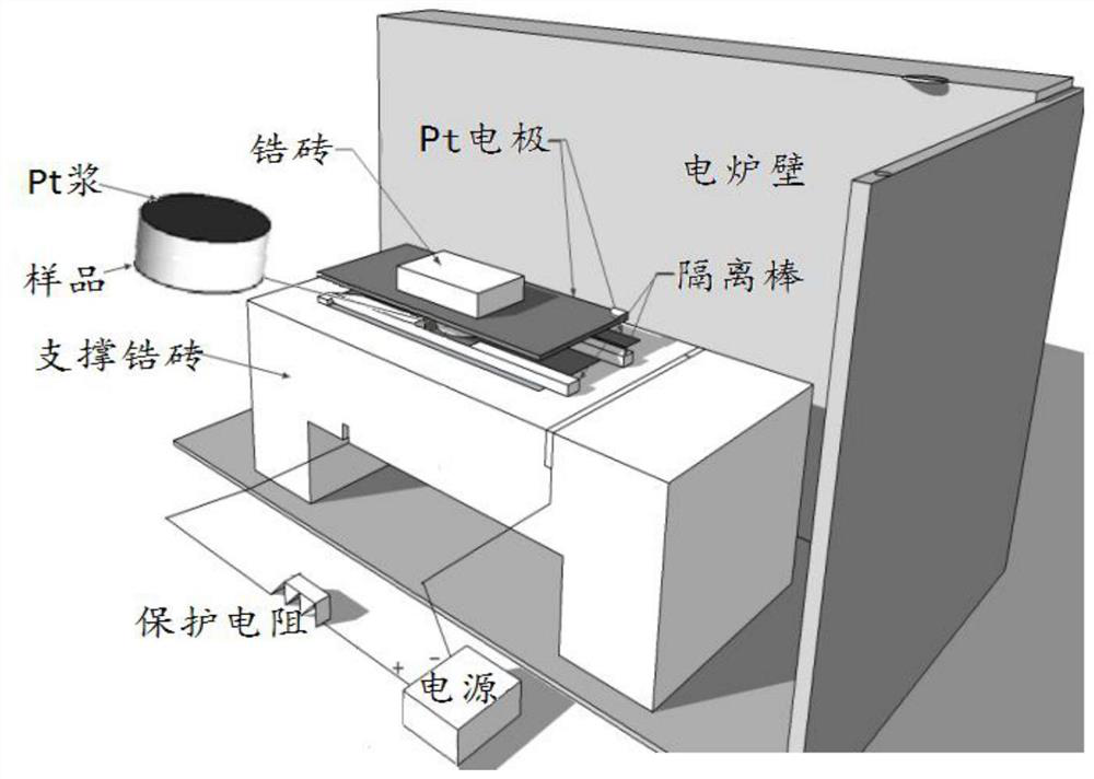
[0027] b. the composite perovskite ceramics prepared in step a is annealed, specifically as follows: see figure 1 , apply Pt slurry on both sides of the composite perovskite ceramics, and put Pt wire electrodes on both sides of the composite perovskite ceramics and press them with zirconium bricks. After supporting the above composite perovskite ceramics with zirconium bricks, put the Pt wire The electrodes are drawn out of the electric furnace, connected to the positive and negative poles of the AC power supply, and then an alternating electric field (about 700V) is applied through the AC power supply. Example) The composite perovskite ceramics were annealed for 100-180min at high temperature (120min is the optimum, and the ...


PUM


Abstract

The invention discloses a method for inducing an ordered domain structure in a complex perovskite by an electric field. Carry out according to the following steps: a. prepare composite perovskite ceramics according to the conventional process; b. anneal the composite perovskite ceramics prepared in step a, specifically as follows: coat Put Pt slurry on both sides of the composite perovskite ceramics and put Pt wire electrodes on both sides and press them with zircon bricks. After supporting the above composite perovskite ceramics with zircon bricks, lead the Pt wire electrodes out of the electric furnace and connect them to AC power Positive and negative electrodes, then apply an alternating electric field through an AC power supply, and at the same time, anneal the composite perovskite ceramics at a temperature of 700°C to 900°C for 100 to 180 minutes. After the annealing is completed, the desired finished product is obtained. The invention has the advantages of low annealing temperature, short annealing time and obvious improvement of the Q value of ceramics.

Description

technical field [0001] The invention relates to a preparation method of a composite perovskite material used in the microwave field, in particular to a method for inducing an ordered domain structure in a complex perovskite by an electric field. Background technique [0002] For composite perovskite materials, the A-site or B-site cations are arranged in a 1:1 or 1:2 order in the <111> direction of the crystal to form a long-range ordered domain structure, which can strongly affect its dielectric loss Q value . For example, I.M.Reaney et al. studied the Ba(Zn1 / 3Ta2 / 3)O3-Sr(Ga1 / 2Ta1 / 2)O3 composite perovskite system and found that the 1:2 long-range ordered domain structure of Zn2+: Ta5+ was sintered at 1525°C 2 hours and annealed at 1275°C for 24 hours can be formed. The Q value (at 2.0GHz) of the annealed sample can be increased from 54000GHz to 78000GHz. M.P.Seabra's research shows that in (1-x)La(Mg0.5Ti0.5)O3-xCaTiO3 composite perovskite, when the CaTiO3 content ...

Claims


Application Information

Patent Timeline
Patent Type & Authority Patents(China)
IPC IPC(8): H01L43/10C04B41/88
CPCC04B41/5122C04B41/88C04B41/4539C04B41/0072
Inventor 胡明哲冯俊杰张续文尹跃
Owner GUIZHOU MINZU UNIV
Why Eureka
Try Eureka