Method of sending a packet through a node

a node and packet technology, applied in the field of sending packets through nodes, can solve the problems of high operational overhead, inability to statistically share capacity, and limited and relatively expensive capacity of tdm circuits, and achieve the effects of avoiding capacity bottlenecks of tdm systems, low cost and high capacity

Active Publication Date: 2007-10-16
ADVA OPTICAL NETWORKING LTD
View PDF3 Cites 2 Cited by
  • Summary
  • Abstract
  • Description
  • Claims
  • Application Information

AI Technical Summary

Benefits of technology

[0003]The capacity bottleneck of the TDM system may be avoided by migrating to a high-capacity packet-based access infrastructure, such as Ethernet. Ethernet equipment is low cost, high capacity, and widely deployed in the industry. Ethernet switches forwards packets based on the destination address. Ethernet switches are intended for friendly enterprise environments and include a number of automatic features in order to easy the installation and operation of the network. However, these automatic features become problematic in large scale operator environments. The automatic features do not scale to large infrastructures and needs sometimes to be disengaged to increase security. This requires manual configuration of possibly a large number of individual units. One specific example of an automatic feature of an Ethernet switch is that they dynamically learn each unique source address of the packets received in order to optimize the forwarding of traffic. It is sometimes necessary to disengage this learning process to prevent customers from being able to communicate directly with each other without going through a service provider.

Problems solved by technology

This TDM circuit, with limited and relatively expensive capacity, is a bottleneck.
The access circuit is provisioned separately from the provisioning of the network service (for example an IP service), leading to high operational overhead.
When several circuits are aggregated in the TDM access network, statistical sharing of capacity is not possible due to the fixed nature of TDM circuits.
The channelized TDM interfaces include complex hardware that monitors each circuit individually but makes line cards expensive.
However, these automatic features become problematic in large scale operator environments.
In summary, problems with basic Ethernet switches include: no support for customer separation; low degree of security due to the fact that cross traffic directly between end-customers is allowed; dynamic address learning may open up for DoS attacks; requires distributed element management and service creation due to the fact that a potential large set of distributed units needs to be configured and managed; and the standard based Spanning Tree Protocol (STP) based restoration is slow.

Method used


Image

  • Method of sending a packet through a node
  • Method of sending a packet through a node
  • Method of sending a packet through a node

Examples


Embodiment Construction

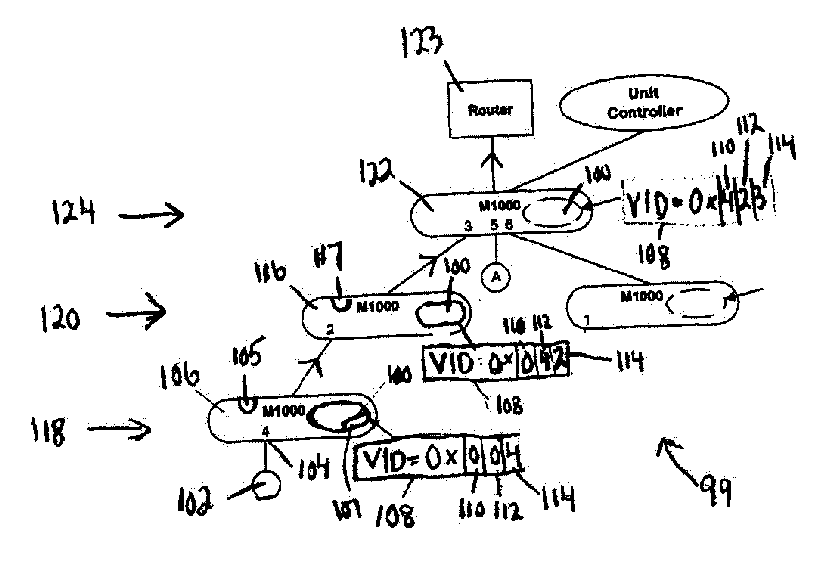
[0018]In general, the method of the present invention includes the steps of adding a tag and port numbers when the packet moves upwardly in a tree topology towards edge equipment such as a router or switch, i.e. in an ingress direction, so that each node shifts previous port numbers and adds a port number before forwarding the node. When the packet moves from a router downwardly in the tree topology, i.e. in an egress direction, each node removes the port number of the outgoing access port from the tag and shifts the subsequent port numbers within the tag.

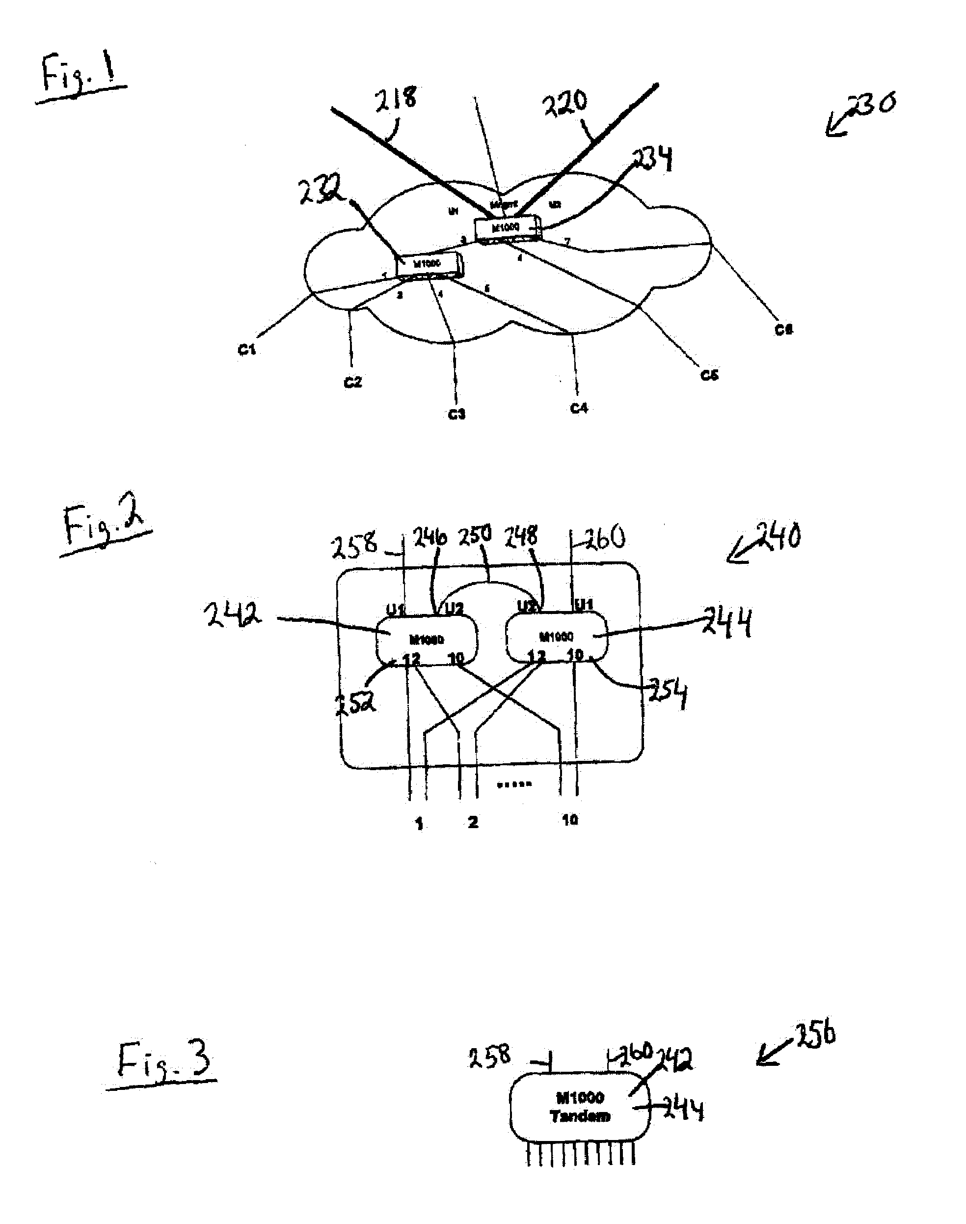
[0019]With reference to FIG. 1, the physical topology 230 may include Marvin node units 232, 234. A tree structure may be used to aggregate the customer traffic in several steps towards a hub node. A daisy-chain of Marvin multiplex units 232, 234 can be used to simplify the build out when a tree is unsuitable or to reduce the amount of fiber or copper links as well as the number of router or switch interfaces. The units 232, 234 ca...


PUM


Abstract

The method is for sending information through a node and includes providing a node that has a first access port, a second access port, a first uplink and a second uplink. A first packet is sent via the first access port to the node. When the node is in a leaf mode, the node creates a tag inside the first packet. The tag contains a first port number corresponding to the first access port. When the node is in a branch node, the node adds the first port number to the tag and sends the packet in the first uplink and the second uplink. A second packet, received via the second access port, is sent via the first uplink of the node. The node receives the second packet. The node removes a second port number that corresponds to the second access port from the tag. The node sends the second packet via the second access port to another node or customer lower down in the node tree.

Description

BACKGROUND OF INVENTION[0001]The method of the present invention relates to sending a packet through a node including both ingress and egress traffic.SUMMARY OF INVENTION[0002]Metro networks are often organized in two levels including metro access and metro core systems. Metro access networks are deployed near the end customer while metro core networks aggregate several access networks deployed in different parts of the metro area. The metro core systems also host the gateway(s) to the wide area backbone network. Currently the dominating technology to connect individual customers and businesses to the Internet is a leased 1.5 or 2.0 Mbps TDM circuits from the customer premises to the provider edge node, that is, a router or a switch, located in the point-of-presence (POP). The edge equipment is populated with channelized TDM interface cards. This TDM circuit, with limited and relatively expensive capacity, is a bottleneck. The access circuit is provisioned separately from the provis...

Claims


Application Information

Patent Timeline
Patent Type & Authority Patents(United States)
IPC IPC(8): H04L12/28G06F15/173H04L12/56
CPCH04L12/2852H04L12/2856H04L47/31H04L45/04H04L45/02
Inventor ORAVA, FREDRIKRAMFELT, LARS
Owner ADVA OPTICAL NETWORKING LTD
Why Eureka
Try Eureka