
Image processing system using rotatable surveillance camera

Inactive Publication Date: 2007-10-16
SUMITOMO ELECTRIC IND LTD
View PDF11 Cites 5 Cited by
  • Summary
  • Abstract
  • Description
  • Claims
  • Application Information

AI Technical Summary

Benefits of technology

[0012]It is therefore an object of the present invention to provide an image processing system capable of detecting physical quantities with high accuracy with the use of a rotatable surveillance camera by allowing mode setting to be switched between an automatic monitoring mode for automatically monitoring an object and a manual remote operation mode that enables acquisition of a picture taken by the surveillance camera with any desired field of view by manual remote operation, and allowing the orientation of the camera to be accurately measured by means of image processing in the automatic monitoring mode.
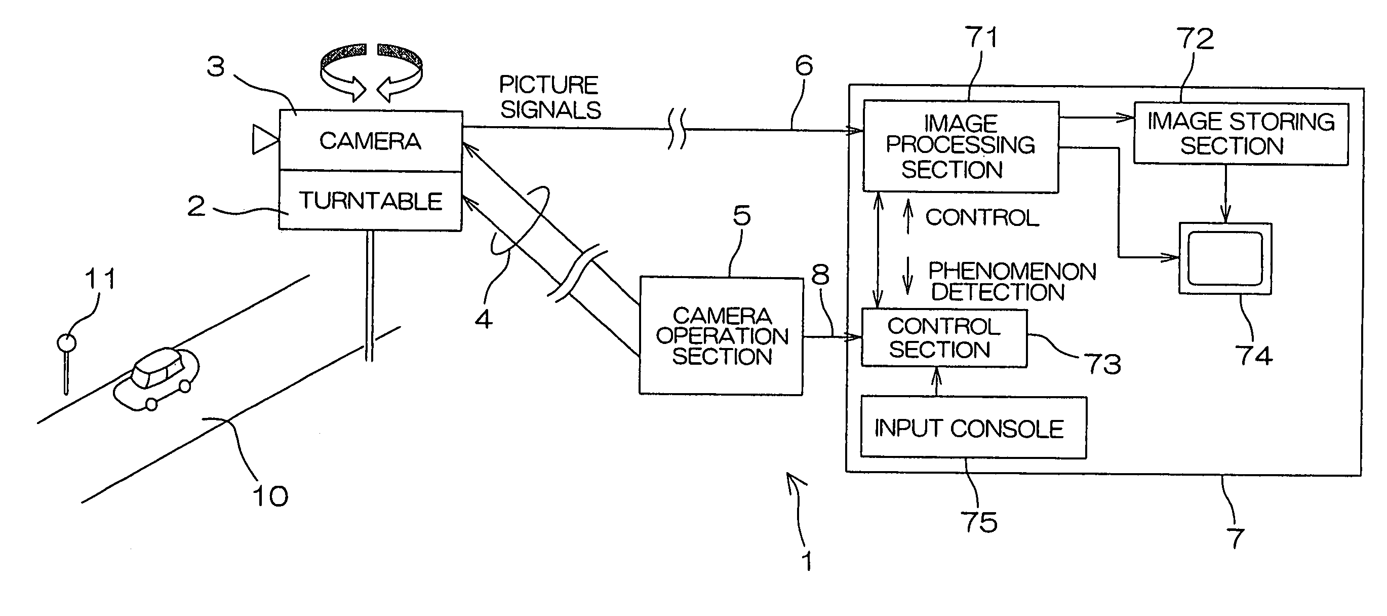
[0014]According to the foregoing structure, in the automatic monitoring mode, the image processing apparatus recognizes on a screen a plurality of reference points whose locations on the road are given, calculates orientation parameters of the surveillance camera based on the positions of the reference points on the screen, and detects a physical quantity of the object based on a photographed image of the object using the orientation parameters. With this arrangement, orientation parameters are accurately calculated, allowing physical quantities such as the position and speed of the object to be measured accurately.
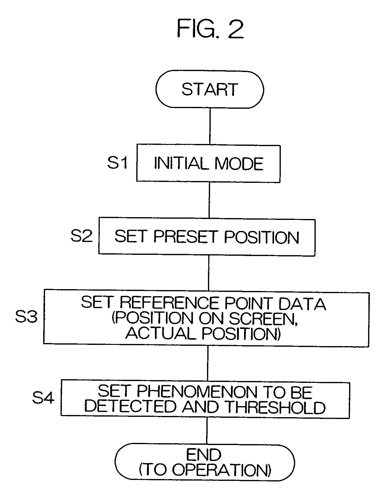
[0015]The arrangement may be such that the surveillance camera is fixed to a preset position in the automatic monitoring mode. This allows images to be automatically monitored constantly with the same field of view. Also in this case, there may be an error in the orientation parameters when switching the mode from the manual remote operation mode to the automatic monitoring mode. However, owing to the aforementioned function of the image processing apparatus, orientation parameters can be calculated accurately, allowing physical quantities such as the position and speed of the object to be measured accurately.
[0019]Switching to the manual operation mode is preferably performed automatically in response to a remote control operation of the camera in the camera operation section as a trigger. If an abnormality phenomenon occurs during the automatic monitoring, the mode automatically switches to the manual operation mode in response to the operator's operation of the camera, so that labor of the operator can be reduced.
[0023]As described so far, according to the present invention, in the automatic monitoring mode, the image processing apparatus recognizes on a screen a plurality of reference points whose locations on a road are given, calculates orientation parameters corresponding to rotation angles of the surveillance camera based on the positions of the reference points on the screen, and detects a physical quantity of the object based on a photographed image of the object using the orientation parameters. Thus, orientation parameters are accurately calculated, allowing physical quantities such as the position and speed of the object to be measured accurately. As a result, even if an error occurs in the orientation of the surveillance camera when switching the mode from the manual operation mode to the automatic monitoring mode, such an error is permissible. Accordingly, it is not necessary to provide the turntable with a precise tracking mechanism, so that the whole structure of the image processing system can be constructed easily at low cost.

Problems solved by technology

Also in this case, there may be an error in the orientation parameters when switching the mode from the manual remote operation mode to the automatic monitoring mode.

Method used


Image

  • Image processing system using rotatable surveillance camera
  • Image processing system using rotatable surveillance camera
  • Image processing system using rotatable surveillance camera

Examples


Embodiment Construction

[0032]A specific embodiment of the present invention will be hereinafter described in detail with reference to the appended drawings.

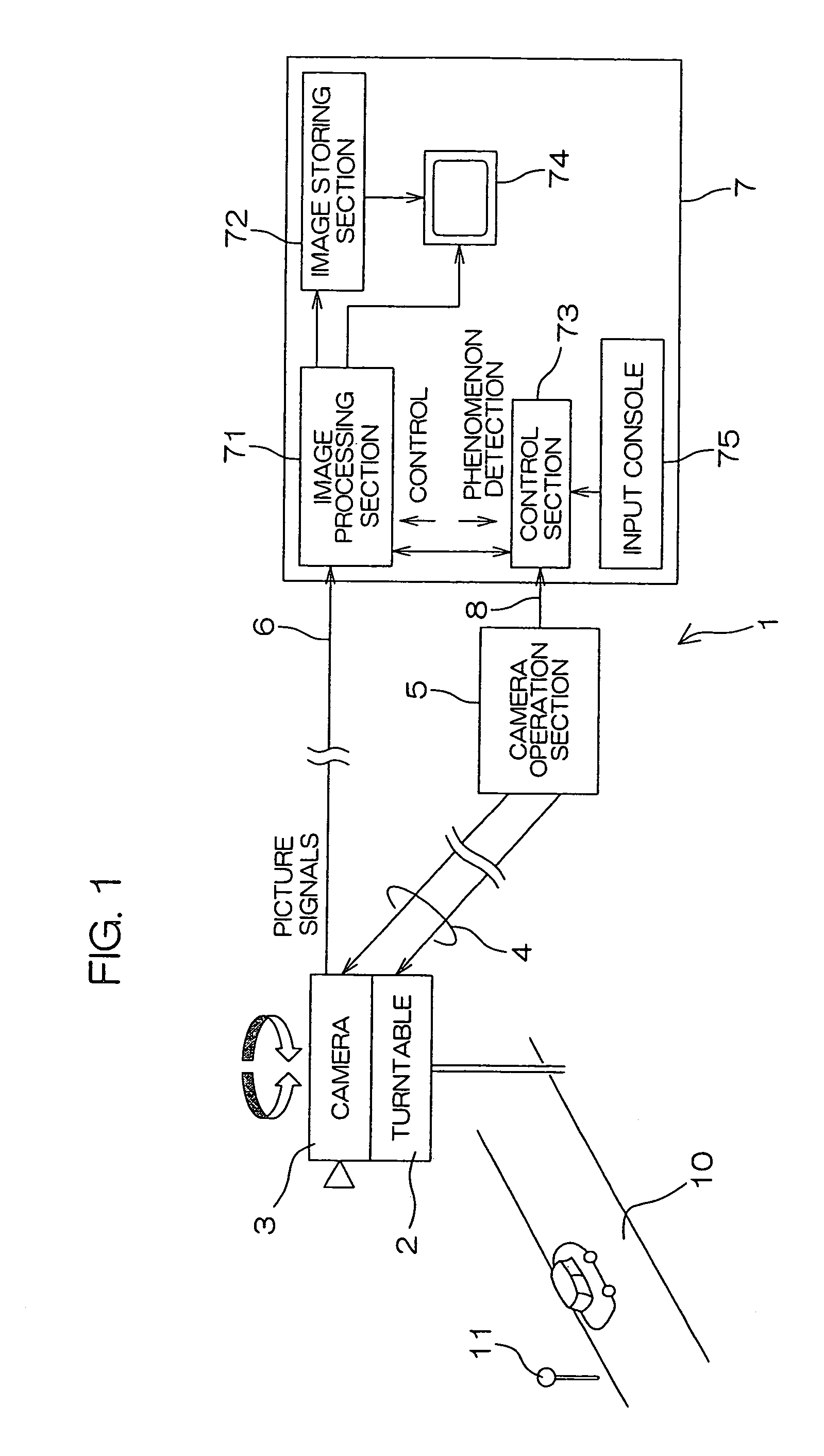
[0033]FIG. 1 is a schematic diagram showing the configuration of an image processing system 1 using a surveillance camera 3 according to the present invention.

[0034]The image processing system 1 is used for monitoring road traffic, and provided with combined functions including a function of automatically monitoring phenomena such as traffic congestion at a fixed field of view and a function of photographing the road with any desired field of view by manual remote operation.

[0035]The image processing system 1 is fixed, for example, to a location overlooking a road 10, and includes a turntable (also called “camera platform”) 2 for varying the orientation of a surveillance camera 3, and the surveillance camera 3 mounted on the turntable 2.

[0036]The turntable 2 can be rotated by a motor about two horizontal axes and a vertical axis. The angles of rotation...


PUM


Abstract

The disclosed image processing system detects the position and speed of a vehicle with high accuracy by accurately measuring the orientation of a rotatable surveillance camera 3 by means of image processing. This system allows mode setting to be switched between an automatic monitoring mode and a manual operation mode. When the mode is switched from the manual operation mode to the automatic monitoring mode, an image processing apparatus 7 recognizes on a screen a plurality of reference points 11 whose locations on a road are given, calculates orientation parameters of the surveillance camera 3 based on the positions of the reference points on the screen, and detects the position and speed of the vehicle based on photographed images of the vehicle using the orientation parameters, thereby detecting phenomena such as traffic congestion and accidents.

Description

[0001]This application is based on application No. 2002-335452 filed in Japan, the content of which is incorporated hereinto by reference.BACKGROUND OF THE INVENTION[0002]1. Field of the Invention[0003]The present invention relates to an image processing system that allows automatic monitoring of objects using a rotatable surveillance camera.[0004]2. Description of the Related Art[0005]Stationary automatic surveillance cameras are installed on roads for measuring traffic congestion and the like on the roads, in which image data of the camera are processed to automatically detect phenomena such as traffic congestion.[0006]Meanwhile, there are also movable-type rotational surveillance cameras installed on roads to take pictures at any desired magnification and field of view by manual remote operation.[0007]The automatic surveillance cameras mentioned first are aimed at detecting abnormalities on the roads with high accuracy, and for image processing reasons, their field of view and ma...

Claims


Application Information

Patent Timeline
IPC IPC(8): G06K9/00G06T7/00H04N7/18G08G1/04
CPCH04N7/188G06T7/0042G06T7/73
Inventor TAMOTO, SHIGETOSHIITO, YOSHIYUKINISHIYAMA, KAZUTO
Owner SUMITOMO ELECTRIC IND LTD
Learn More