
Integrated air separation and oxygen fired power generation system

a power generation system and air separation technology, applied in the direction of liquefaction, machines/engines, lighting and heating apparatus, etc., can solve the problems of system operation power costs as high as 50% of the overall operational cost, and the emerging total production cost of products, so as to reduce power requirements

Inactive Publication Date: 2007-10-23
LAIR LIQUIDE SA POUR LETUDE & LEXPLOITATION DES PROCEDES GEORGES CLAUDE +1
View PDF23 Cites 131 Cited by
  • Summary
  • Abstract
  • Description
  • Claims
  • Application Information

AI Technical Summary

Benefits of technology

[0013]Accordingly, it is an object of the present invention to provide an integrated air separation and power generation system that that reduces power requirements during system operation.
[0014]It is another object of the present invention to configure the power generation system for the air separation unit such that power requirements for the air separation unit are lower in comparison to utilizing a conventional on-site power plant to operate the air separation unit.
[0015]It is a further object of the present invention to provide an integrated air separation and power generation system that efficiently integrates heat during system operation and optimizes turbine configuration for providing power to the main air compressor of the air separation unit.

Problems solved by technology

However, a drawback to a cryogenic air separation system is that power costs associated with system operation can run as high as 50% of the overall operational costs, where most of the power is consumed by the main air compressor disposed upstream of the air separation unit.
Accordingly, the power costs associated with the main air compressor have a strong influence on the total production cost of the products emerging from the air separation unit.

Method used


Image

  • Integrated air separation and oxygen fired power generation system
  • Integrated air separation and oxygen fired power generation system
  • Integrated air separation and oxygen fired power generation system

Examples


Embodiment Construction

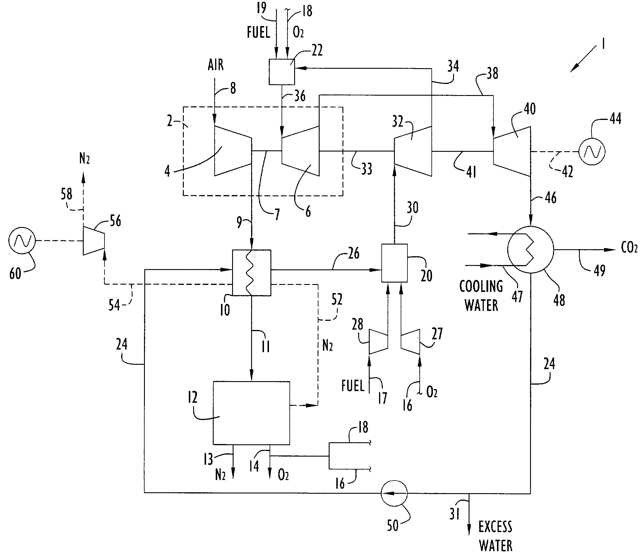
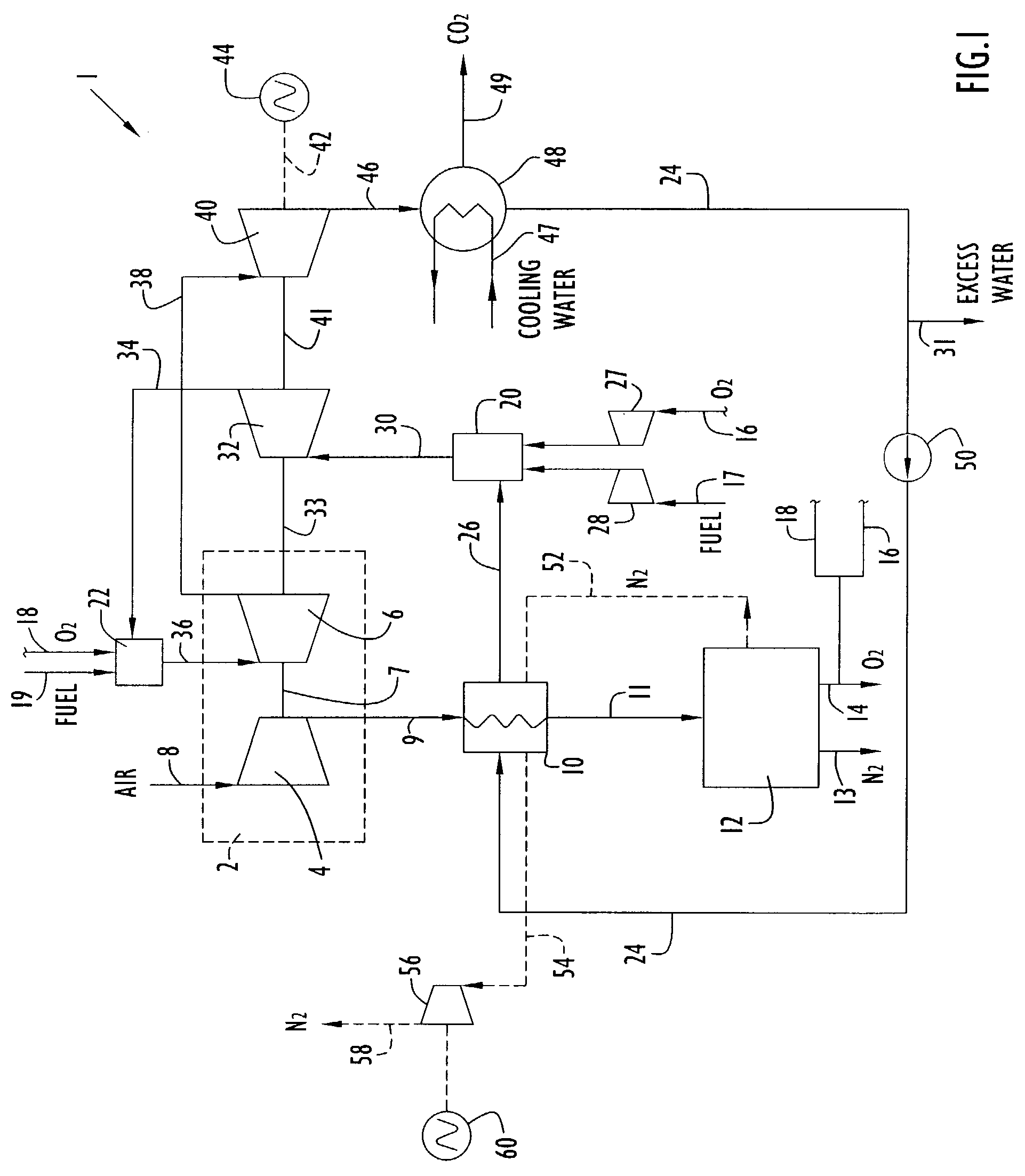
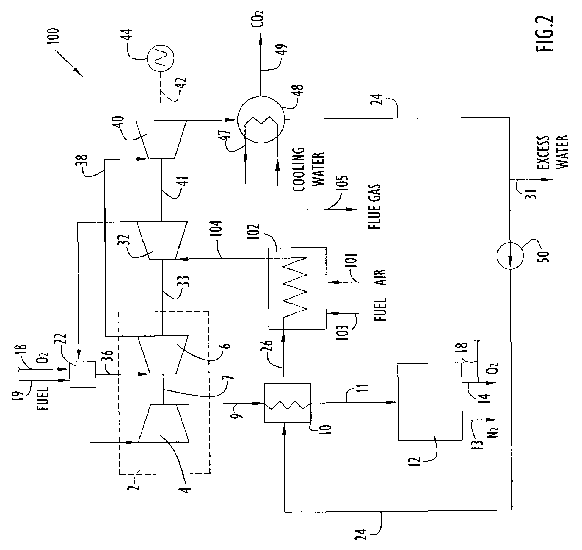
[0023]An integrated air separation and power generation system includes an air separation unit (ASU) that receives compressed air from an air compressor of a gas turbine. The gas turbine further includes a gas turbine expander coupled (e.g., via a shaft) to the air compressor to facilitate the direct transfer of mechanical energy from the expander to the compressor during system operation. One or more additional turbines are also integrated into the system in an optimized manner to further deliver power to the air compressor so as to provide air to the ASU in an efficient and cost-effective manner as described below. An exemplary type of ASU for use in the system is a cryogenic system. However, the ASU may include any one or more other systems suitable for separating two or more combined gas and / or liquid components including, without limitation, membrane systems and adsorption systems.

[0024]The power generation system preferably includes one or more combustion units to provide supp...


PUM


Abstract

An integrated air separation and oxygen fired power generation system includes an air separation unit and a gas turbine including an air compressor to provide compressed air for the air separation unit. The system further includes a gas turbine expander and at least one additional turbine to drive the air compressor, as well as at least one combustion unit to provide drive gas for expander and additional turbine(s). A portion of oxygen produced by the air separation unit is delivered to the combustor(s) to facilitate production of drive gas for use by the expander and additional turbine(s). Turbine inlet temperatures are controlled by recycling water or steam to the combustor(s).

Description

CROSS REFERENCE TO RELATED APPLICATION[0001]This application claims priority from U.S. Provisional Patent Application Ser. No. 60 / 356,105, entitled “Integrated Air Separation Unit and Oxygen-Fired Power Generation System” and filed Feb. 11, 2002. The disclosure of the above-mentioned provisional application is incorporated herein by reference in its entirety.BACKGROUND OF THE INVENTION[0002]1. Technical Field[0003]The present invention pertains to air separation units combined with oxygen fired power generation systems.[0004]2. Discussion of the Related Art[0005]Cryogenic air separation is typically preferred in the industry for yielding large volumes of oxygen and nitrogen, which may then be used in variety of different power generation systems. However, a drawback to a cryogenic air separation system is that power costs associated with system operation can run as high as 50% of the overall operational costs, where most of the power is consumed by the main air compressor disposed u...

Claims


Application Information

Patent Timeline
Patent Type & Authority Patents(United States)
IPC IPC(8): F02C6/00F01K21/04F01K23/06F25J3/04
CPCF01K21/042F01K23/064F25J3/04018F25J3/04121F25J3/04127F25J3/04533F25J3/04581F25J3/04618F01K21/047Y02E20/18F25J2230/06F25J2230/20F25J2240/70F25J2260/80Y02E20/14Y02E20/34
Inventor MARIN, OVIDIUMACADAM, SCOTTFILLET, FREDERICDI ZANNO, PIETRO
Owner LAIR LIQUIDE SA POUR LETUDE & LEXPLOITATION DES PROCEDES GEORGES CLAUDE
Learn More