Sedimentation removal assembly for flow-through sedimentary tank

a sedimentary tank and assembly technology, applied in sedimentation settling tanks, liquid displacement, separation processes, etc., can solve the problems of affecting the stability of sedimentation, and presenting a more difficult problem in the removal of solids, and being particularly troublesom

Active Publication Date: 2007-10-23
AERO MOD
View PDF8 Cites 60 Cited by
  • Summary
  • Abstract
  • Description
  • Claims
  • Application Information

AI Technical Summary

Problems solved by technology

However, removal of the solids presents a more difficult problem.
They are accordingly very susceptible to resuspension by any turbulence caused by a sludge or solids removal mechanism at the base of the sedimentation tank.
Again, this is particularly troublesome in the case of lightweight flocs.
Such devices have the advantage of positive removal of solids, but suffer from the disadvantage of physically moving a scraper or the like through already settled materials.
When the material is light and fluffy, this movement resuspends the solids which will slip over the top of the scrapers and also create undesirable currents within the sedimentation zone.
This system has the disadvantage that in order to create slopes for solids to settle, the surfaces need to be at least 60° relative to the horizontal, and the solids need to be smooth to facilitate collection thereof.
There becomes a practical limit on how deep this hopper can be because the hopper extends upwardly into the sedimentation tank at an angle of 60° or more.
Another disadvantage of this type of system is that the settled solids tend to “bridge” within the hopper zone, with the pump then removing only clear liquid while the solids compact and build up above the “bridge.” In order to keep this from happening, the pump is often run continuously to prevent bridging.
However, when this is done, too much liquid is removed with the solids.
When the solids are removed from the excess liquid during downstream processing, the removed liquid must be returned to the sedimentation tank, increasing the hydraulic load on the system and decreasing the capacity thereof.

Method used


Image

  • Sedimentation removal assembly for flow-through sedimentary tank
  • Sedimentation removal assembly for flow-through sedimentary tank
  • Sedimentation removal assembly for flow-through sedimentary tank

Examples


Embodiment Construction

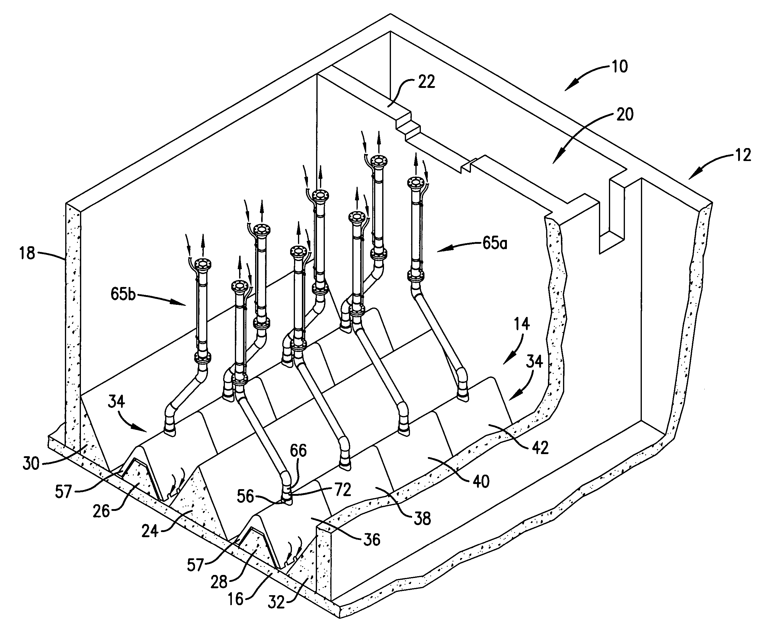
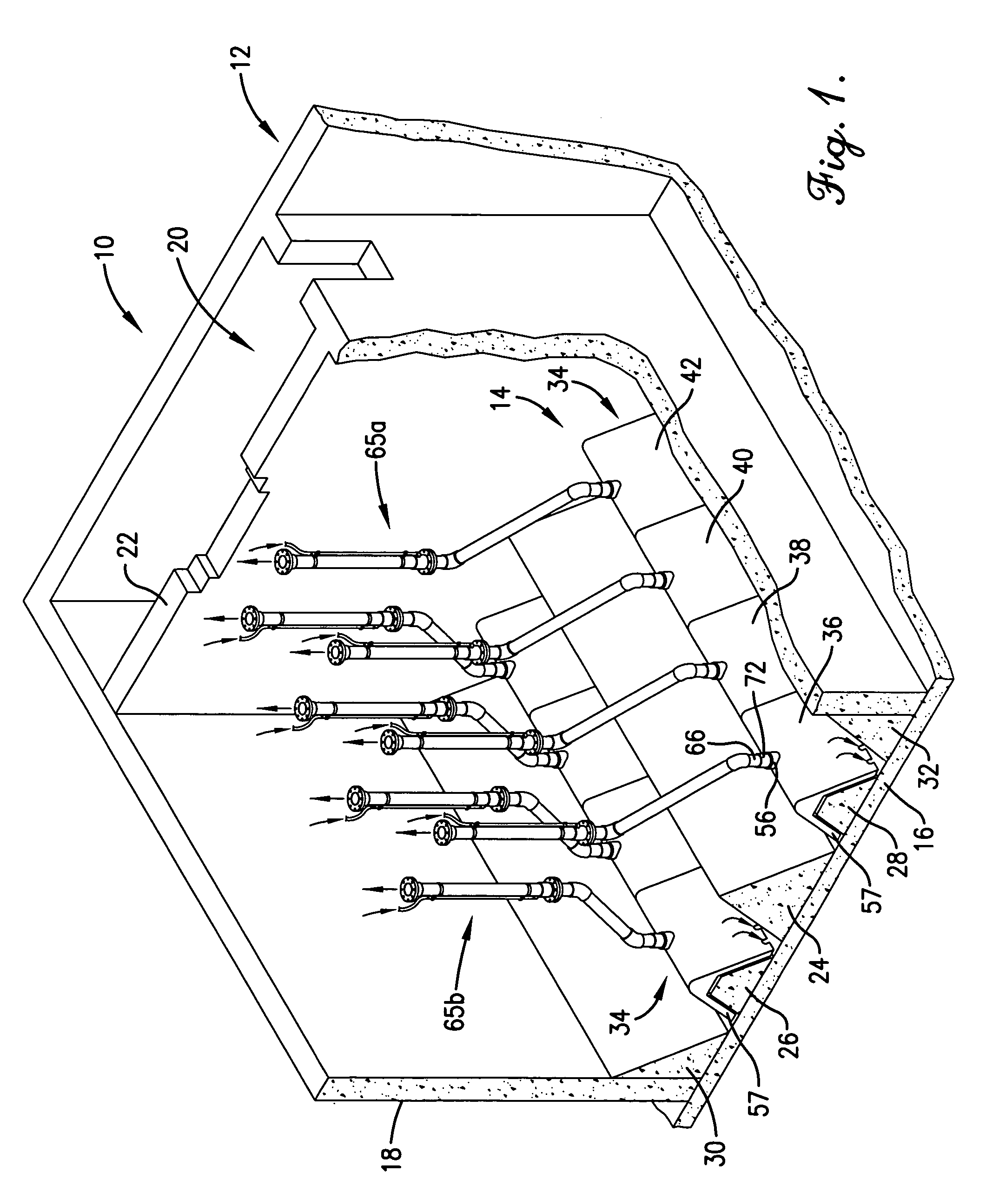
[0017]Turning now to the drawings, FIG. 1 illustrates a sedimentation tank assembly 10 broadly including an upright sedimentation tank 12 as well as a plurality (here two) of sedimentation removal assemblies 14 located adjacent the bottom of the tank 12. The assembly 10 is designed to efficiently remove solids of various densities from incoming waste water as a part of treatment thereof. The overall assembly 10 is similar in many respects with the clarifier assembly described in U.S. Pat. No. 5,035,795 incorporated by reference herein, particularly in the details of construction relating to waste water inlets and outlets. That is, the present invention is particularly directed to the improved, below water level assemblies 14, and these may be employed in a variety of different types of sedimentation or other solids removal tank systems.

[0018]In more detail, the tank 12 is formed of poured concrete and includes a bottom wall 16 as well as upstanding tank-defining sidewalls 18. The ta...


PUM

PropertyMeasurementUnit
angleaaaaaaaaaa
angleaaaaaaaaaa
vertical heightaaaaaaaaaa

Abstract

Solids removal assemblies (14) adapted for use in flow-through or batch-type sedimentation tanks (12) are provided which increase the efficiency of solids removal and eliminate physical scraping devices common with such sedimentation tanks. The preferred removal assemblies (14) include an elongated hood (34) disposed over a cooperating and complementally configured fill structure (26,28), which fills the majority of the internal volume of the hood (34). The hood (34) includes converging sidewalls (44, 46) having lower most inlet openings (54) and spaced, tubular outlets (56) adjacent the apex thereof. Outlet pipes (64) are operably coupled with each of the hood outlets (56) for suction withdrawal of waste water-solids suspensions which are then conveyed for downstream processing. The hood (34) and fill structure (26, 28) cooperatively define restricted flow paths for the waste water-solids suspensions, and assist in the creation of relatively high velocity movement of the suspensions to prevent bridging or clogging by collective solids adjacent the bottom of the tanks (12).

Description

BACKGROUND OF THE INVENTION[0001]1. Field of the Invention[0002]The present invention is broadly concerned with improved solids removal assemblies used in various types of sedimentation tank systems in order to more efficiently remove solids from incoming waste water streams. More particularly, the invention is concerned with such solids removal assemblies, as well as methods of operation and complete solids removal systems incorporating the solids removal assemblies. The preferred solids removal assemblies include an elongated hood having converging sidewalls together with an elongated fill structure located within the housing; a plurality of upright outlet pipes are operatively coupled to the hood for withdrawal of liquid-solid suspensions drawn into the hood, permitting downstream processing of the suspension.[0003]2. Description of the Prior Art[0004]A sedimentation tank forming a part of sewage or other waste water treatment facility is typically a tank designed to receive inco...

Claims


Application Information

Patent Timeline
Patent Type & Authority Patents(United States)
IPC IPC(8): B01D21/24
CPCB01D21/02B01D21/245B01D21/2466
Inventor SCHMID, LAWRENCE A.
Owner AERO MOD
Why Eureka
Try Eureka