Holding device for disk-shaped objects

Active Publication Date: 2007-10-23
ONTO INNOVATION INC
View PDF25 Cites 39 Cited by
  • Summary
  • Abstract
  • Description
  • Claims
  • Application Information

AI Technical Summary

Benefits of technology

[0012]The object of the present invention is to provide a holding device which on the one hand ensures a secure hold of the object both during standstill

Problems solved by technology

This wafer chuck, can, for instance, not be positioned overhead, because the wafer would not be securely retained in all positions.
This holding de

Method used


Image

  • Holding device for disk-shaped objects
  • Holding device for disk-shaped objects
  • Holding device for disk-shaped objects

Examples


Example

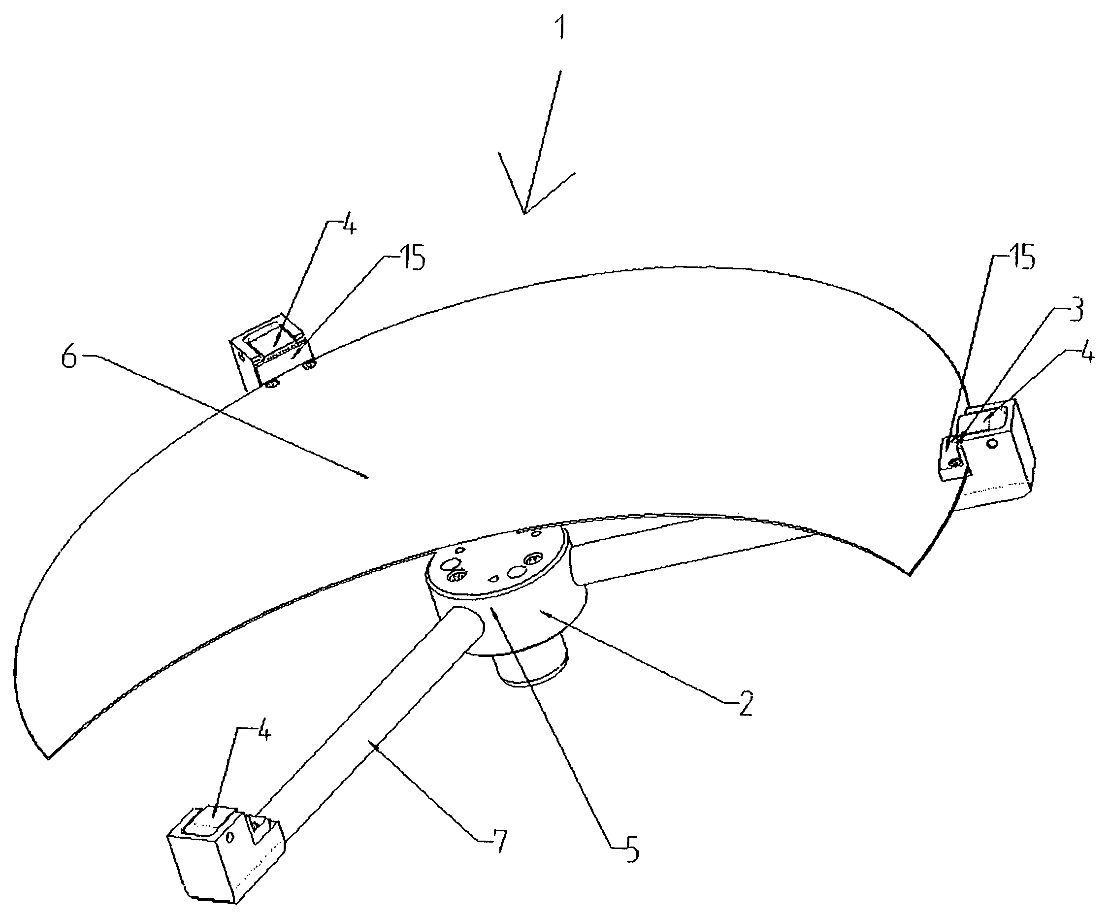
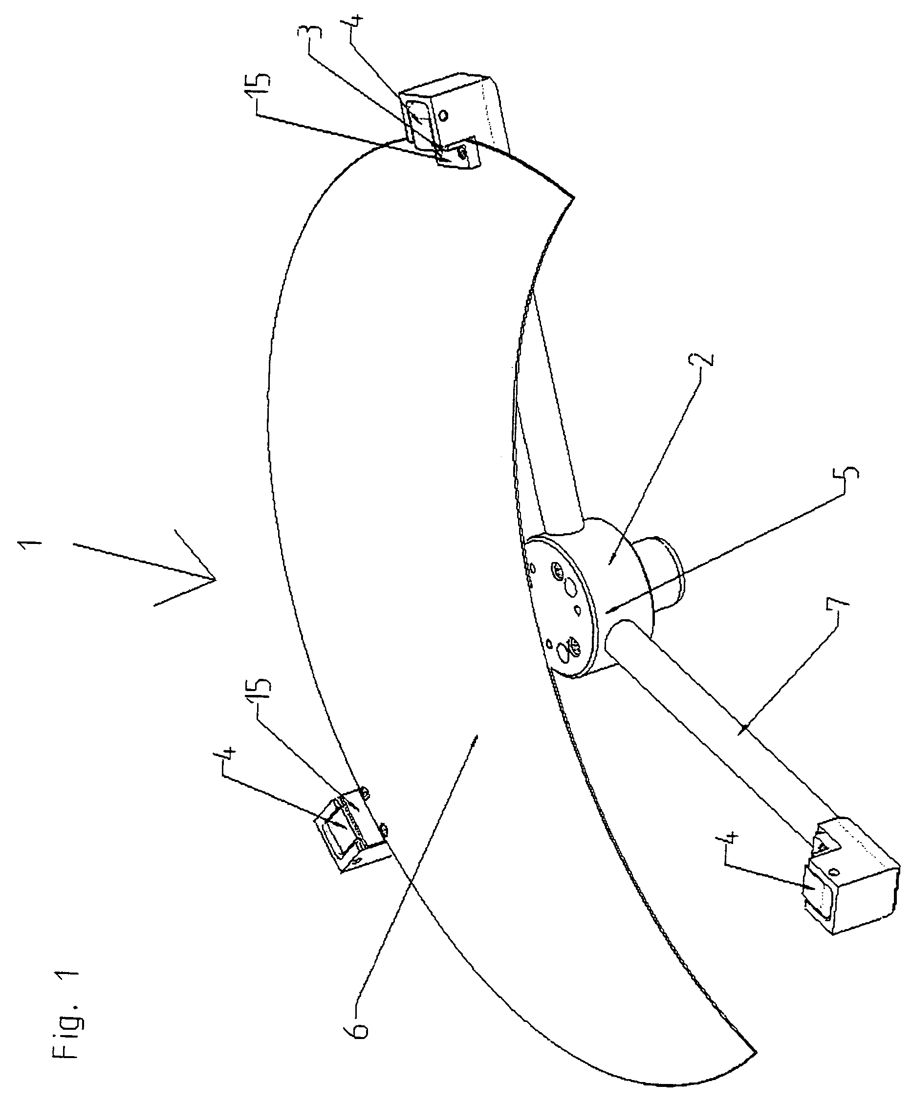
[0054]FIG. 1 shows a holding device 1 for wafers. The holding device 1 comprises three clamping arms 7. The clamping arms 7 are radially arranged on a central clamping arm fixture 2 toward the outside. In addition, the central clamping arm fixture 2 incorporates a vacuum feed-thru 5 for actuating the vacuum-powered opening mechanisms 100 that are incorporated in each clamping arm 7. Support elements 15 with a support surface 3 for the wafer (not shown) as well as swivel-mounted gripper fingers 4 are grouped on the outer ends of the clamping arms 7. The support surfaces 3 also serve for pre-centering the wafer when it is placed onto the holding device 1. The support element 15 as well as the gripper finger 4 are shown with dotted lines. A shielding disk 6 is also shown. This shielding disk 6 between the clamping arms 7 and the wafer is provided to protect the wafer against potential particles.

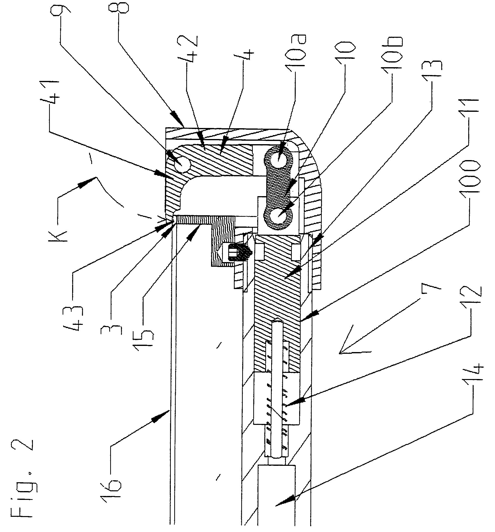
[0055]FIG. 2 shows the assembly of a vacuum-powered opening mechanism 100. The wafer 16 rest...


PUM

PropertyMeasurementUnit
Timeaaaaaaaaaa
Pressureaaaaaaaaaa
Diameteraaaaaaaaaa

Abstract

Semiconductor technology requires the use of object holders, which are capable of holding wafers securely, also during rotation. In order to save time and expense, such holders should be suitable for integration directly into a processing facility, wherever possible. According to the invention it is proposed to provide centrally mounted holders which comprise support surfaces for the wafer and pivotable gripper fingers, in which the gripper fingers are pretensioned by means of at least one pretension element in the holding position and are actuated through one opening mechanism, in which at least one opening mechanism and at least one pretension element are integrated in the central clamping arm fixture and/or in the clamping arms.

Description

FIELD OF THE INVENTION[0001]The invention relates to a holding device for disk-shaped objects, specifically wafers, with at least two centrally mounted clamping arms, which comprise support surfaces for the object and pivotable gripper fingers, in which the gripper fingers are pivotable from a clamping position into an opening position and vice versa, each of which are pretensioned in their clamping position with a pretension element and actuated by means of at least one opening mechanism.BACKGROUND OF THE INVENTION[0002]Generic object holders are, for instance, required in semiconductor technology. During the manufacture of semiconductor components, such as computer chips, wafers are coated several times and are chemically treated. In order to distribute reagents homogenously over the wafer or dry the wafer between two processing steps, the wafer is frequently rotated on its own axis. The wafer is frequently also rotated for quality control purposes when optical measuring methods a...

Claims


Application Information

Patent Timeline
IPC IPC(8): B23B31/30B01L9/00H01L21/683B23Q3/00B25B11/00H01L21/68H01L21/687
CPCH01L21/68707Y10T279/1961Y10T279/18Y10T279/1966Y10T279/33Y10T279/1291
Inventor SIEBERT, SONKESCHWEIGER, MICHAELLANG, ANDREAS
Owner ONTO INNOVATION INC
Why Eureka
Try Eureka