

Electromagnetic Retarder For a Motor Vehicle
- Summary
- Abstract
- Description
- Claims
- Application Information
AI Technical Summary
Benefits of technology
Problems solved by technology
Method used
Image

Examples
first embodiment
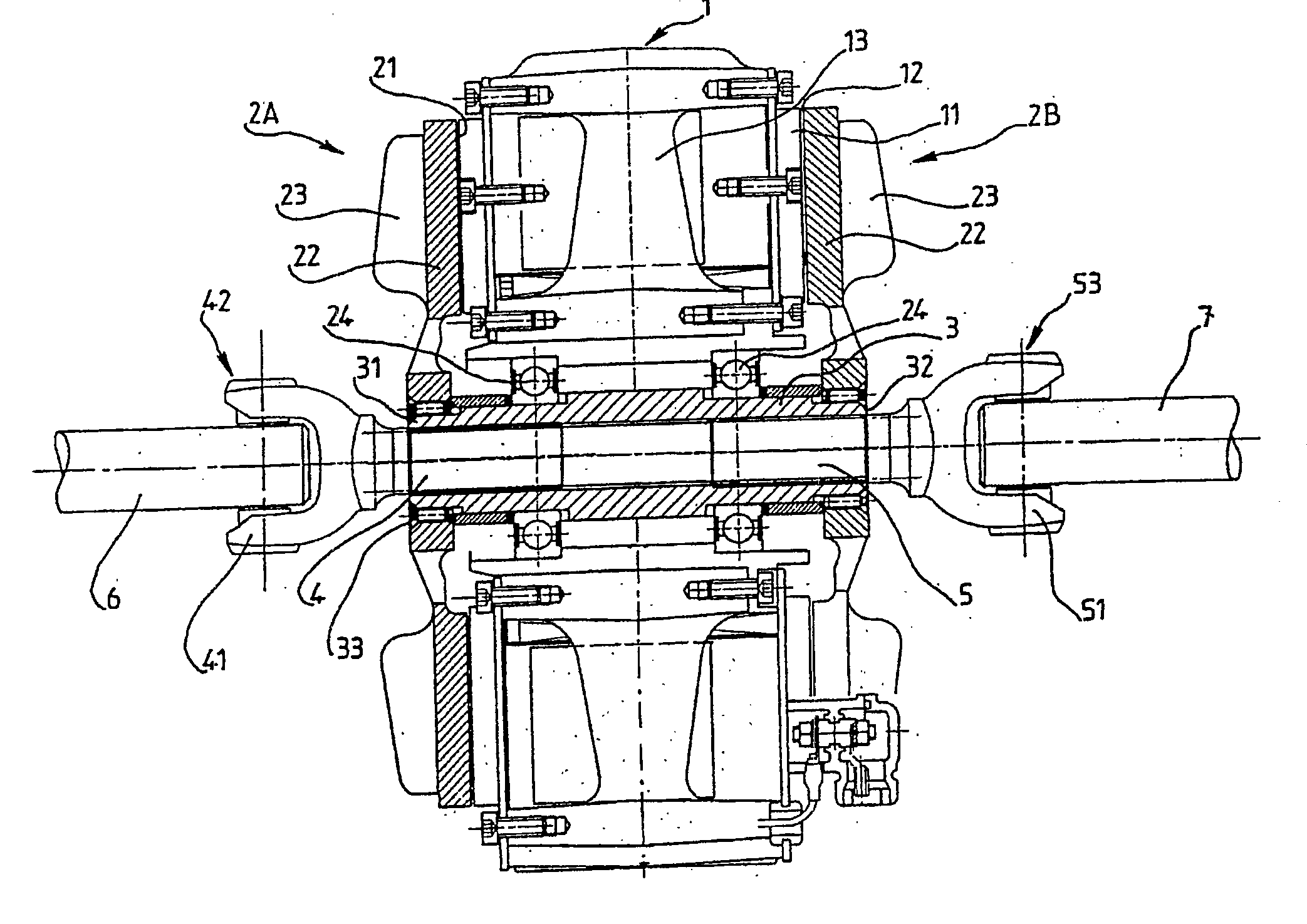
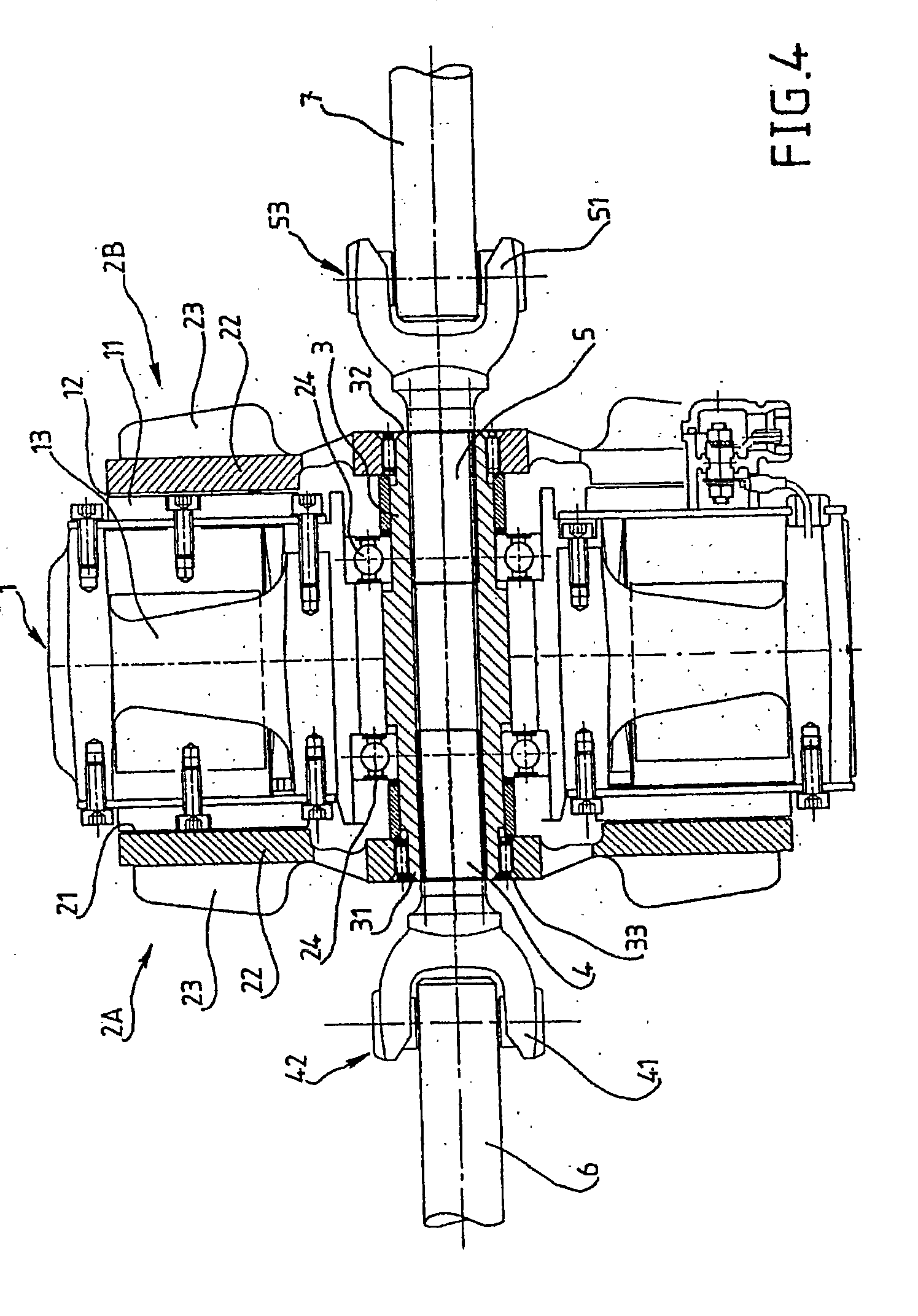
[0064]FIG. 5 shows an alternative of a retarder according to the invention. This retarder comprises a stator 1 and two rotors 2A and 2B, as well as a first shaft 3 of which only first end 31 is configured in such a way that it can receive a shaft, here shaft 4, by hafting in an axially sliding manner. Second shaft 4 is connected, by means of the cardan joint 42, to the propshaft 6 linked to the gearbox of the vehicle.
[0065]According to this alternative embodiment, second end 32 of first shaft 3 is configured in such a way that it can receive a conventional coupling with jaw end AM.
[0066]Whereas shaft 3 is mounted in stator 1 on the side of its first end 31 by means of ball bearings 24, first shaft 3 is mounted on the side of its second end 32 in the rotor by means of roller bearings 26, for example conical roller bearings intended to compensate transversal stress relative to the axial range of first shaft 3.
[0067]Whereas rotor 2 is fitted on first shaft 3 in the first embodiment, il...
second embodiment
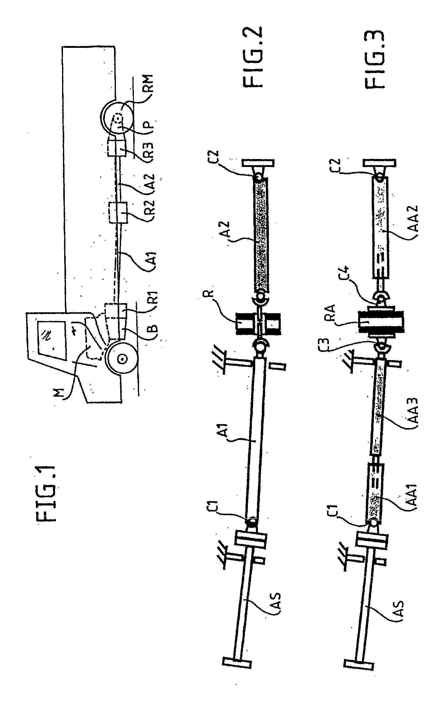
[0068]The electromagnetic retarder of the invention, illustrated in FIG. 6 and according to alternative embodiments illustrated in FIGS. 7 to 9, is a retarder of the Focal type mounted axially on the output shaft 4 of a gearbox B.
[0069]This retarder, as the retarder according to the first embodiment, comprises a stator 1 passed through by a first shaft 3 having a first end 31 and a second end 32, the two ends 31, 32 being axially opposed and coupled respectively to second shaft 4 and propshaft 7 linked to a load, for example to driving wheels RM. The retarder also comprises a rotor 2 assembled with first shaft 3 in order to present an internal cylindrical face 21 in the vicinity of an external cylindrical face 11 of stator 1 with a thin air-gap 12 between stator 1 and rotor 2.
[0070]In this electromagnetic retarder, first shaft 3 is configured at one of these two ends, here at first end 31, in order to be coupled to the corresponding shaft, here the output shaft 4 of gearbox B, in a...
PUM
 Abstract
Description
Claims
Application Information