
Square embossed roof and rib plate

Inactive Publication Date: 2007-10-23
FCI HLDG DELAWARE
View PDF34 Cites 10 Cited by
  • Summary
  • Abstract
  • Description
  • Claims
  • Application Information

AI Technical Summary

Benefits of technology

[0007]It is an object of the present invention to provide a mine roof and rib control that overcomes the deficiencies in the prior art. It is another object of the present invention to provide a new mine roof and rib control that is economical, in that it reduces the amount of scrap, provides greater strength than current bearing plates, and is also easy and safe to handle, bundle, and install.

Problems solved by technology

However, due to the seriousness of the safety issues involved with correctly supporting mine roof and rib strata and the increasing risk of injury caused by mine roof falls, further improvements are desirable.

Method used


Image

  • Square embossed roof and rib plate
  • Square embossed roof and rib plate
  • Square embossed roof and rib plate

Examples


first embodiment

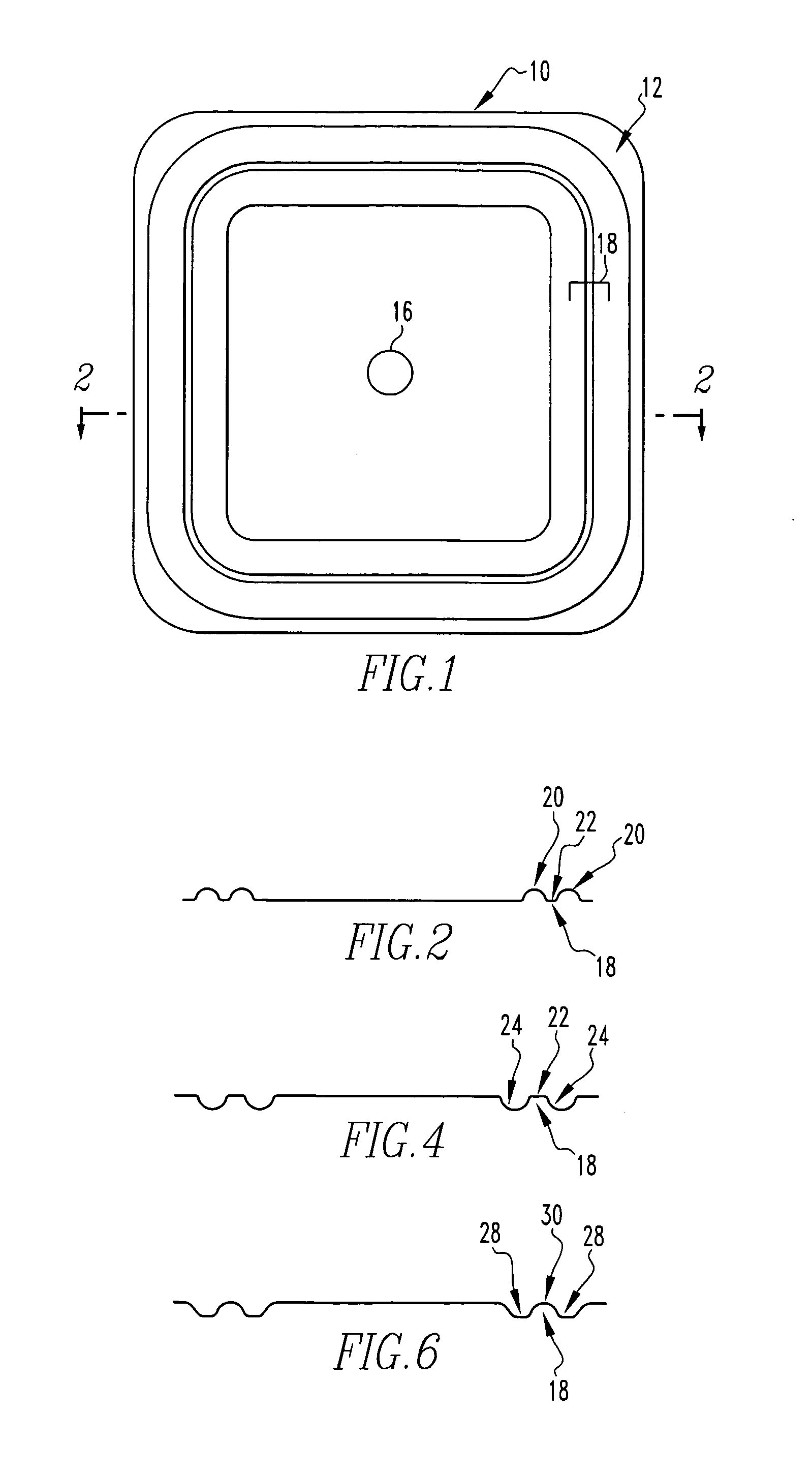
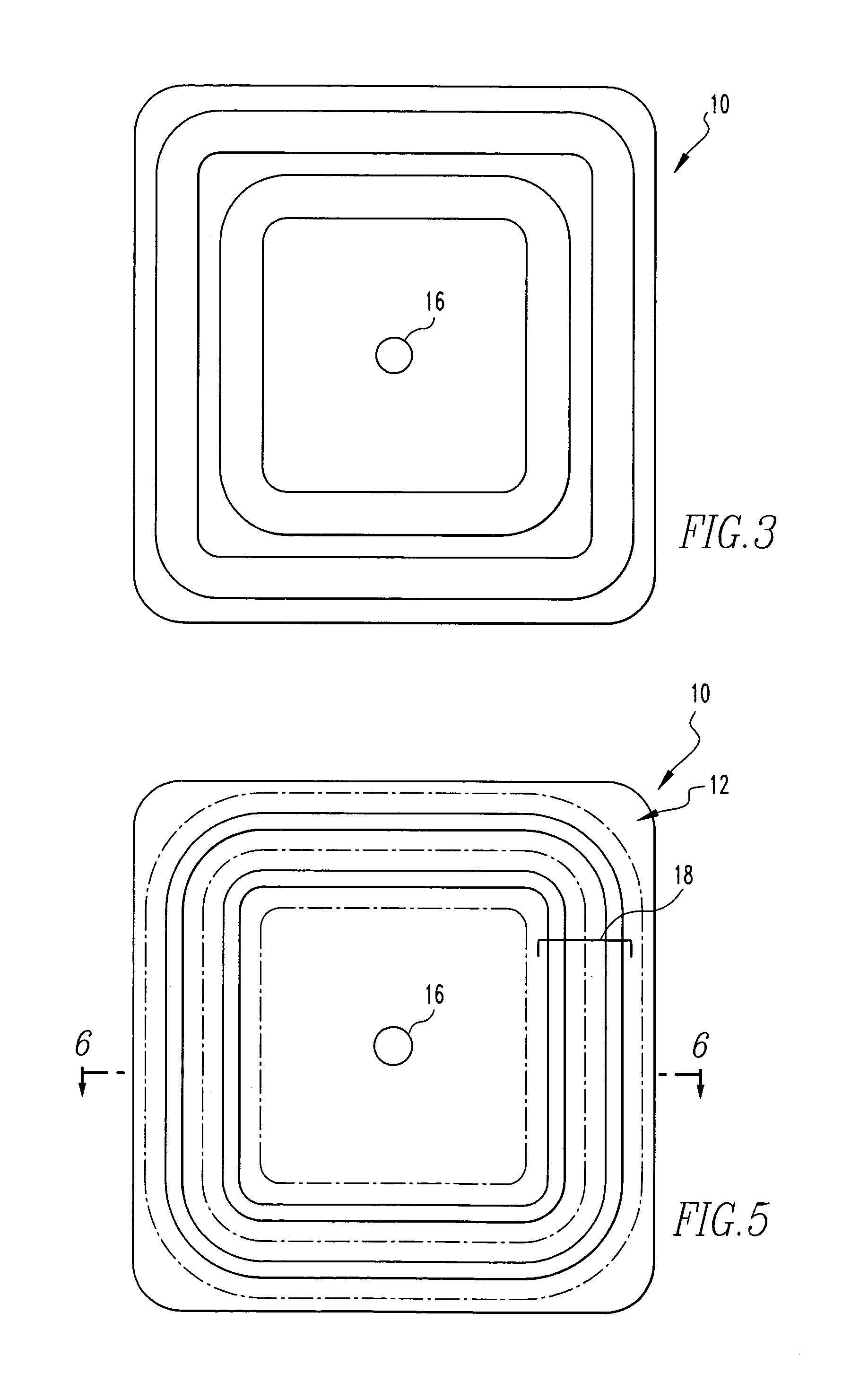
[0030]FIG. 12 illustrates different possible designs FIGS. 12A-12L of the rib member area 18 and the resulting calculated moments of inertia. These tests were used to establish the desired first embodiment that provides the greatest possible strength. Using the established preferred design of the rib member area 18, FIGS. 12A, 12C, 12G, and 12K illustrates a preferred design of the square bearing plate 10 that will provide the greatest strength, yet will allow for a surface area large enough to allow for a 6×6, 8×8, or 6×10 primary support plate, or a substantially similar size elliptical primary support plate to be used in conjunction therewith.

[0031]Any of the aforementioned embodiments are designed to be used with a mine roof bolt to provide mine roof and rib support. Dome-shaped, donut-shaped, flat, or other suitably-shaped mine roof and rib support plates may also be used in conjunction with the square bearing plates 10 according to any of the embodiments of the present inventi...

second embodiment

[0034]The forming of a square bearing plate 10 of the first or second embodiment from a steel strip or sheet has less scrap per piece, yet will cover more surface area, as compared to conventional round bearing plates. This is considered to be one of the greatest advantages of the present invention, in that it provides greater strength at a cheaper cost based on the reduced amount of scrap per piece.

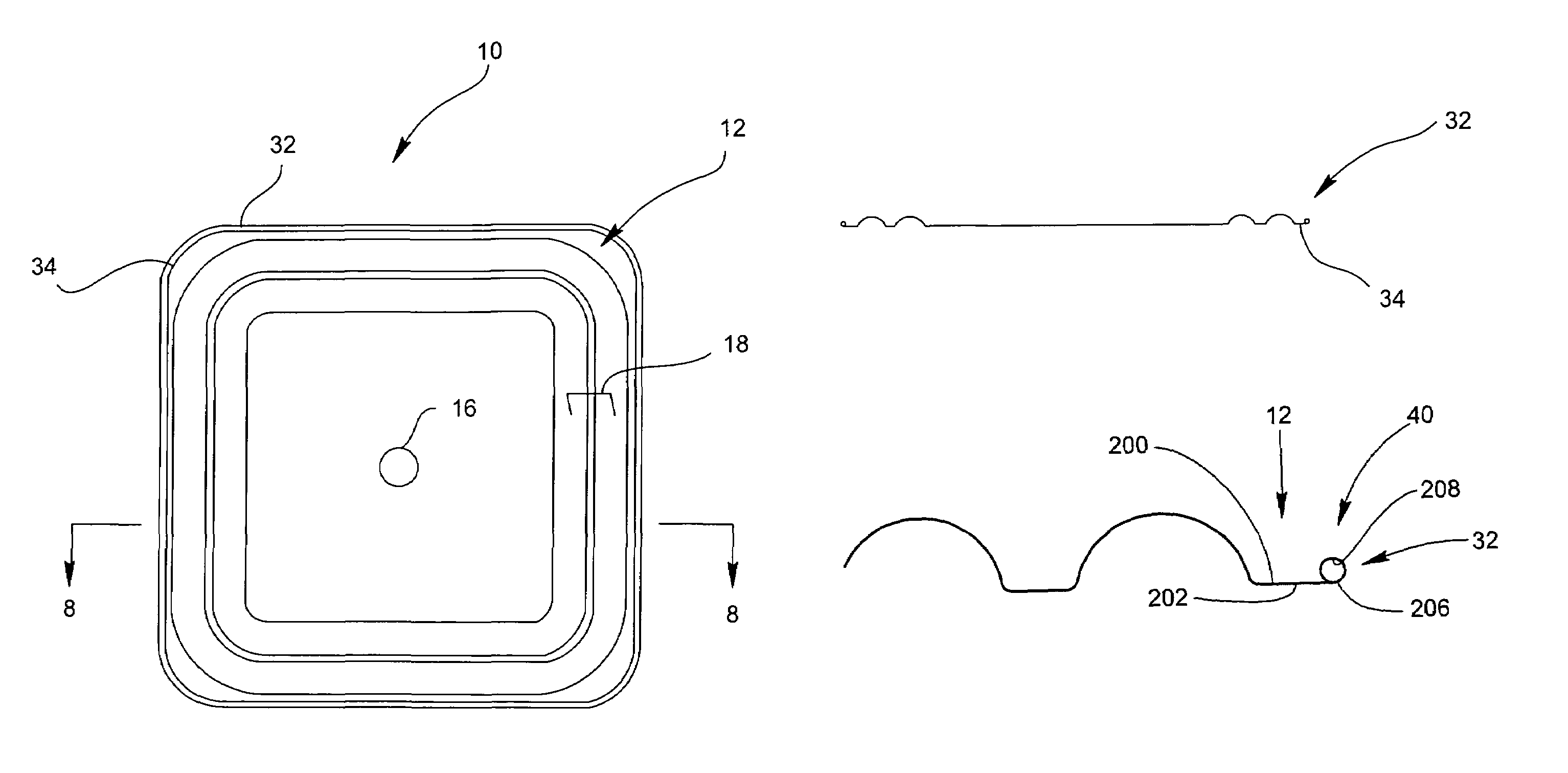
[0035]Referring to FIGS. 15 and 16, in a method of making a mine roof support system according to the present invention, in a first operation 100, a blank (the square bearing plate 10) is formed from raw material, for example, sheet or strip steel. The blank includes the through hole 16, the peripheral section 12, and the rib member area 18. In a second operation 102, the safety edge 32 is formed around the peripheral section 12 of the blank (square bearing plate 10). The first operation 100 is preferably a one-step operation performed by, for example, a first die assembly.

[0036]Preferab...


PUM

PropertyMeasurementUnit
Shapeaaaaaaaaaa
Areaaaaaaaaaaa
Perimeteraaaaaaaaaa

Abstract

Disclosed is a mine roof and rib support system generally including a square bearing plate. A through hole is positioned near a center portion of the square bearing plate. A peripheral section at least partially circumscribes the bearing plate. In between the through hole and the peripheral section is a rib member area. The rib member area may include two rib members with a convex cross-section connected by a substantially linear surface member disposed between the two rib members, two or more concave ribs with a substantially linear surface member disposed between the two rib members, or two substantially linear surfaces connected by a convex rib member. A safety edge surrounds the square bearing plate. The safety edge may be a rolled edge, a looped edge, a folded edge, or another comparable edge. Also disclosed is a method for making the mine roof and rib support system.

Description

CROSS-REFERENCE TO RELATED APPLICATIONS[0001]This application claims the benefit of U.S. Provisional Patent Application Ser. Nos. 60 / 386,939, filed Jun. 7, 2002, and 60 / 395,112, filed Jul. 11, 2002.BACKGROUND OF THE INVENTION[0002]1. Field of the Invention[0003]The present invention generally relates to mine roof and rib supports and, more particularly, to generally square bearing plates used in connection with a mine roof bolt and a primary support member.[0004]2. Description of Related Art[0005]Mine roof and rib (sidewall) control is important for the safety and well being of miners. Surface control is critical to effective roof and rib support systems. Surface control devices with adequate stiffness characteristics can help reduce or even eliminate progressive roof and rib failures. Mine roof and rib controls are typically managed by drilling a bore hole in a mine roof, installing one end of a mine roof bolt in the bore hole, positioning a channel, bearing plate, or mat adjacent ...

Claims


Application Information

Patent Timeline
IPC IPC(8): E02D29/045B21D35/00E21D11/15E21D17/00E21D17/01E21D21/00
CPCE21D11/155E21D21/0086Y10T428/24653
Inventor CALANDRA, JR., FRANKEATON, JACK R.STANKUS, JOHN C.STEWART, EUGENE H.BRANDON, DEMREY G.
Owner FCI HLDG DELAWARE
Learn More