
Medical device control systems

a technology for controlling systems and medical devices, applied in medical science, surgery, diagnostics, etc., can solve problems such as requiring both hands of the physician, affecting the risk of patient trauma, and verbal instructions may be misunderstood

Inactive Publication Date: 2007-10-23
BOSTON SCI SCIMED INC
View PDF15 Cites 117 Cited by
  • Summary
  • Abstract
  • Description
  • Claims
  • Application Information

AI Technical Summary

Benefits of technology

The invention is a system for performing medical procedures using a catheter with a holding portion and an actuating assembly. The actuating assembly can be programmed by the physician to initiate various functions, such as selecting options on a visual display or performing a medical procedure. The system can also respond to the way the actuating assembly is triggered, such as by single or repetitive triggering. Overall, the invention allows for greater control and flexibility for the physician during medical procedures.

Problems solved by technology

In many applications, the ability to steer the catheter is critical to the success of the diagnostic or therapeutic protocol and may affect the risk of trauma to the patient as well.
One drawback of conventional catheters, including catheters used in ablation procedures, is that they may require both of the physician's hands to hold the catheter and manipulate the steering assembly.
Verbal instructions may be misunderstood and, in some instances, may be hard to communicate.
In addition, there is a time delay between the giving of the verbal instruction and the performance of the request.
At least one extra person may be required in the operating room to carry out the physician's instructions, increasing the costs of the procedure and increasing the likelihood of error.

Method used


Image

  • Medical device control systems
  • Medical device control systems
  • Medical device control systems

Examples


Embodiment Construction

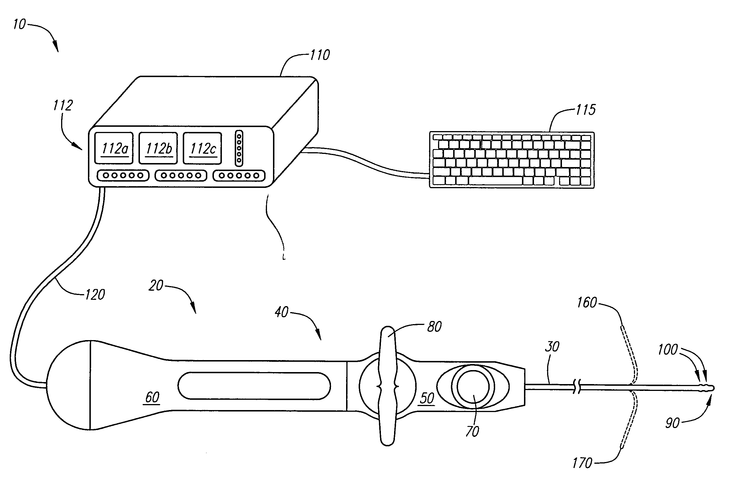
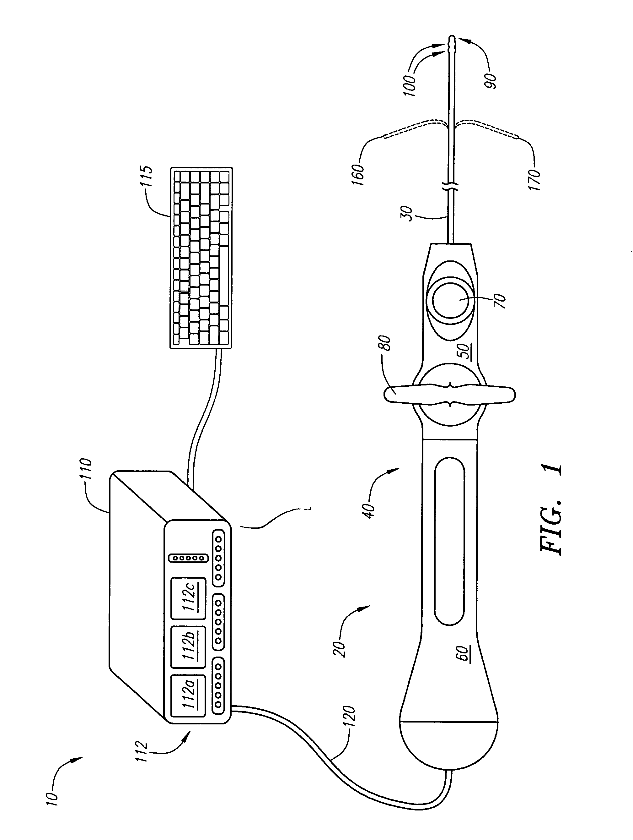
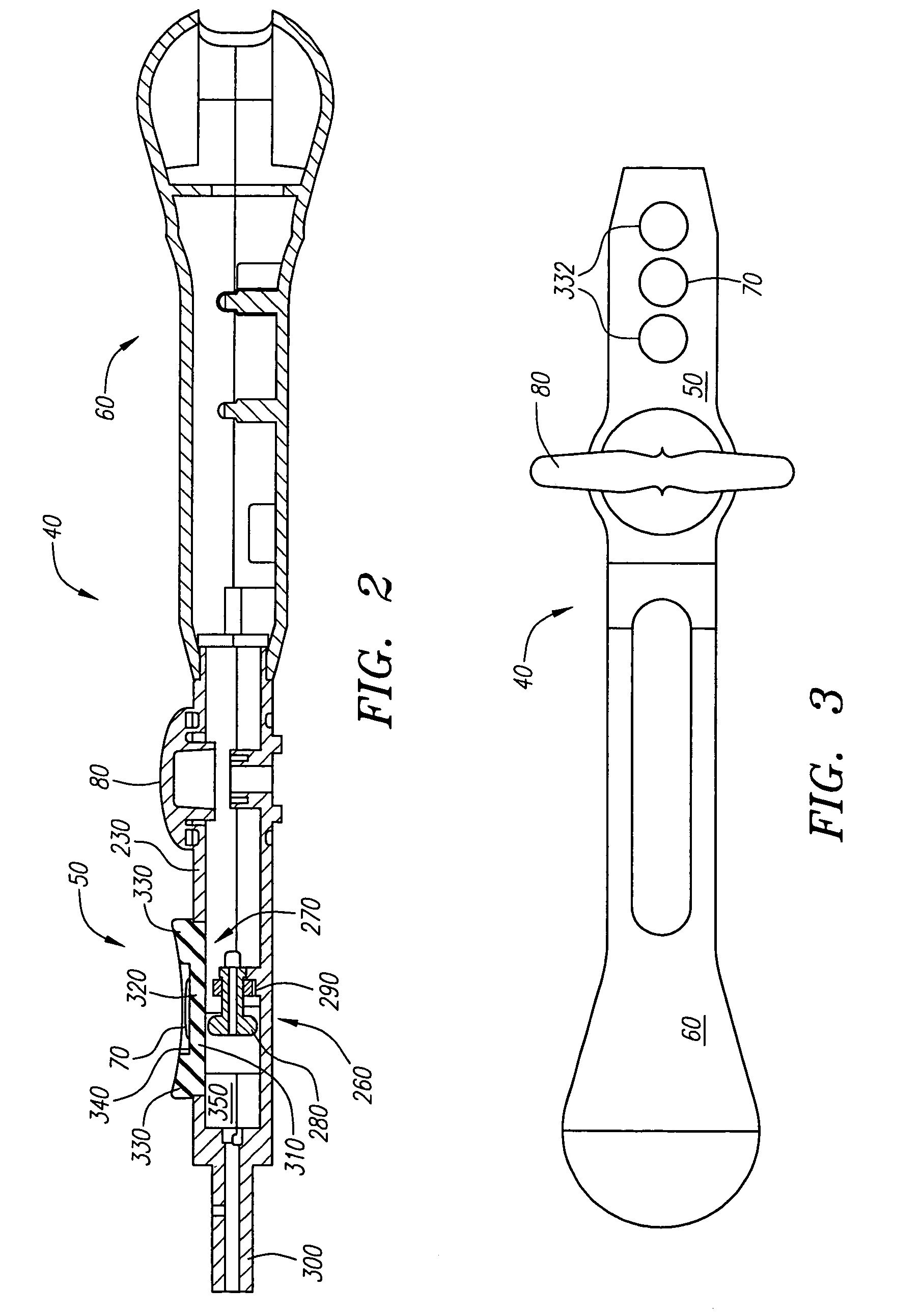
[0039]FIG. 1 illustrates an embodiment of a push button ablation catheter system 10 in accordance with an embodiment of the present invention. The system 10 includes a catheter 20 having a catheter body or shaft 30 and a catheter handle 40. The catheter handle 40 has a distal portion 50, a proximal portion 60, an actuating assembly 70, and a steering assembly 80. The actuating assembly 70 in this embodiment is a push button assembly 70 enabling a physician manipulating the catheter 20 to also directly control other functions of the system, as discussed further below.

[0040]The steering assembly 80 is used to control a distal portion 90 of the catheter body 30 as it is guided through the body's vascular system. The steering assembly 80 is attached to steering wires that extend through an interior lumen of the catheter handle 40 and the catheter body 30. The steering wires are secured to circumferentially spaced elements of the distal portion 90 of the catheter body 30 such that rotati...


PUM


Abstract

A medical device for use by an operator to perform a medical procedure in a body includes a handle to be held by the operator, a shaft attached to the handle and an actuating assembly to control functions associated with the medical procedure. The shaft includes an operative distal portion to perform a medical procedure in the body. The medical device may be part of an ablation catheter system that is programmed to correlate one or more functions with the actuation of the actuating assembly. Multiple actuating assemblies may be provided. Each actuating assembly may be a button. Other types of actuating assemblies may also be used, such as switches or a trackball. The actuating assembly may also be provided on a sleeve that may be selectively attached to the handle of the catheter or the physician operating the catheter, for example.

Description

FIELD OF THE INVENTION[0001]The present invention relates to medical devices, and more particularly, to control systems for medical devices.BACKGROUND OF THE INVENTION[0002]Catheters are often used in medical procedures to provide access to remote locations within a patient. A catheter can be inserted into the patient's body through a small incision and threaded through a blood vessel or other narrow passageway to reach the intended location. Dilatation catheters have been used to open blockages in blood vessels in percutaneous transluminal coronary angioplasty procedures, for example. Various types of catheters are also used in electrophysiology therapies to locate and treat cardiac arrhythmias. For example, one or more catheters may be used to pace, map and ablate cardiac tissue to block the passage of aberrant electrical signals.[0003]Steering mechanisms have been developed to facilitate the transit of catheters through body lumens such as the vascular system. These mechanisms ty...

Claims


Application Information

Patent Timeline
Patent Type & Authority Patents(United States)
IPC IPC(8): A61B18/14A61B5/04A61B17/00A61B18/00
CPCA61B18/00A61B18/1492A61B2018/00916A61B2017/00199A61B2017/00367A61B19/56A61B34/25
Inventor KRUEGER, KATIE L.WOHLGEMUTH, JONBENCINI, ROBERT F.TAIMISTO, MIRIAM H.LARDNER, RICHARD
Owner BOSTON SCI SCIMED INC
Learn More