
Apparatus and method for a chain motivated toaster with vertically aligned rollers

a technology of vertical alignment and apparatus, which is applied in the field of apparatus and method for a chain-motivated toaster with centrally disposed, vertically aligned rollers, can solve the problems of lack of resiliency and reliability, and achieve the effect of facilitating the traversing of said food items

Inactive Publication Date: 2007-10-23
AMERICAN PERMANENT WARE CORP
View PDF13 Cites 14 Cited by
  • Summary
  • Abstract
  • Description
  • Claims
  • Application Information

AI Technical Summary

Benefits of technology

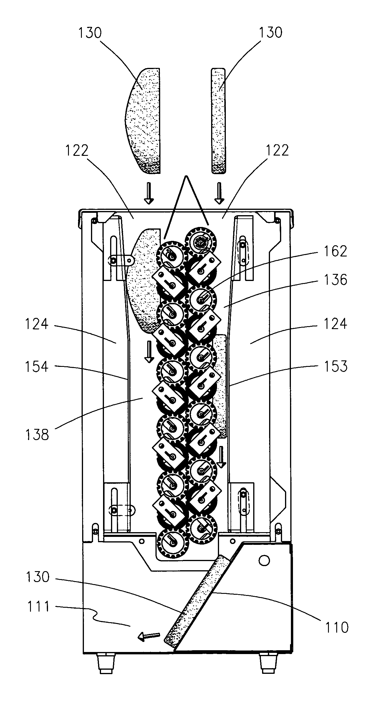
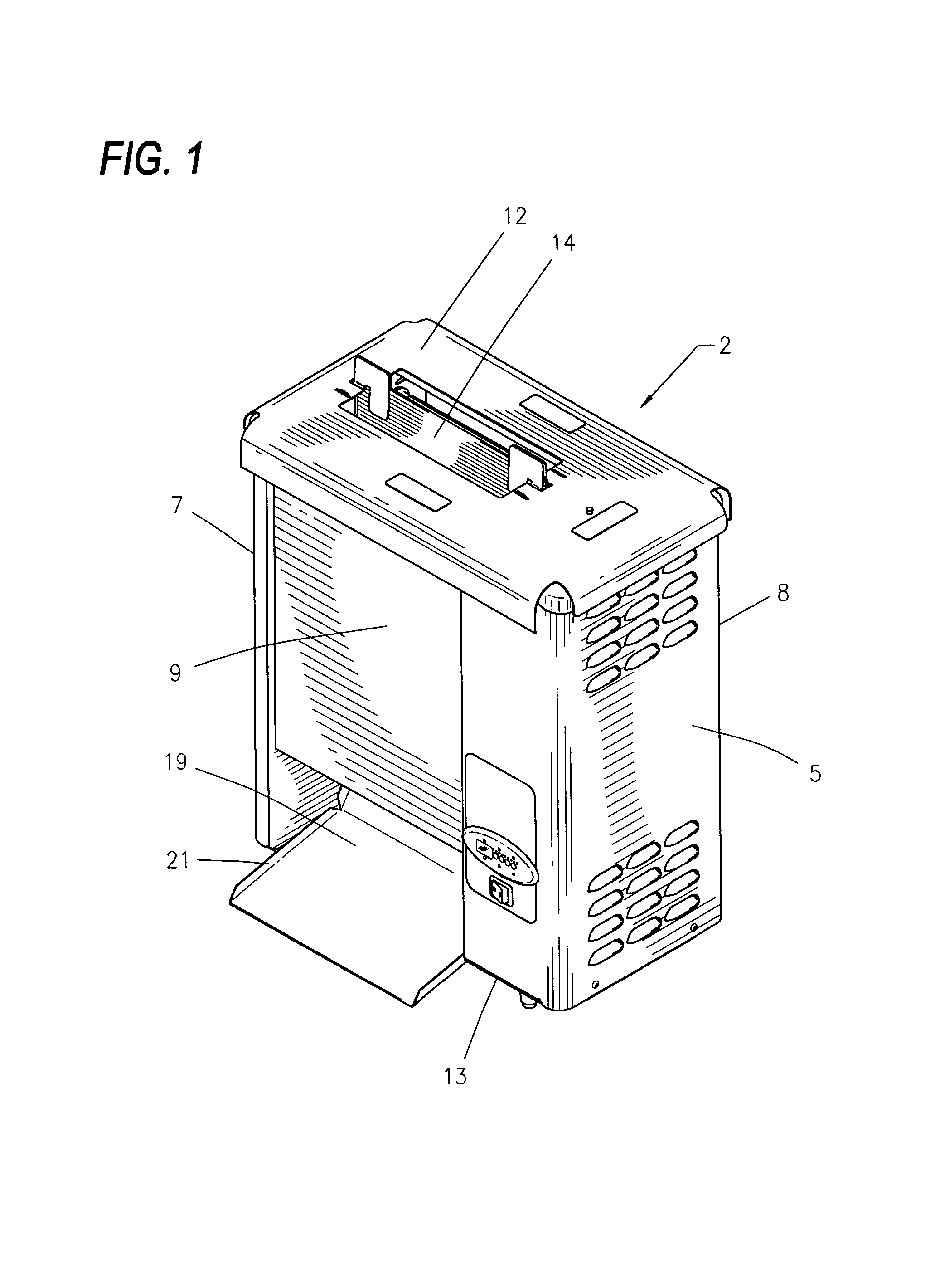
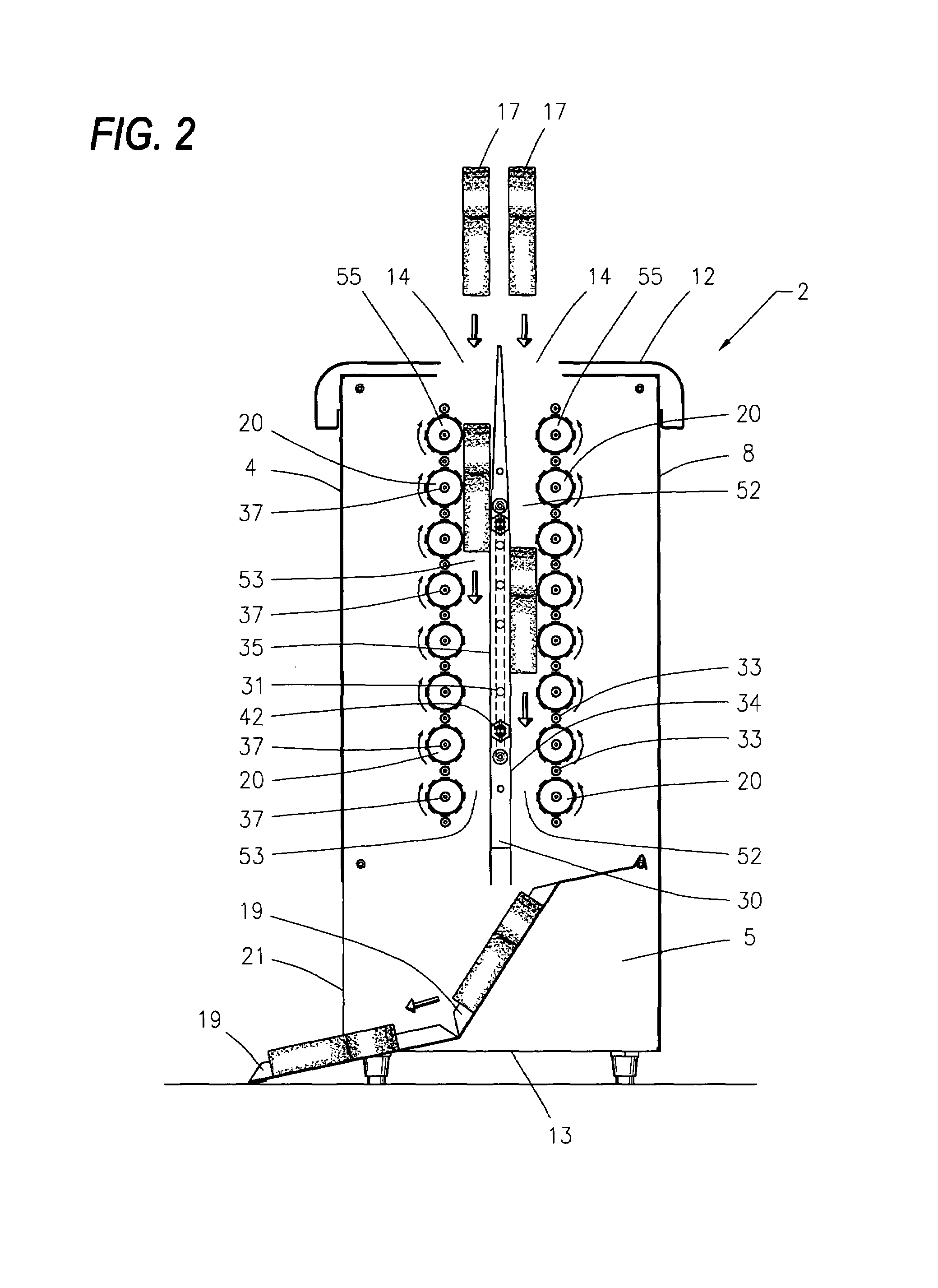
"The present invention is a vertical roller toaster with vertically aligned rollers that are motivated by an electric motor and a chain mechanism. The oven housing has a cavity with heating zones and an exit opening. The oven cavity is formed by a top, bottom, first, second, third, and fourth side portions. Food products enter through the food product inlet openings and are captured by the plurality of vertically aligned rollers and a chain mechanism. The chain mechanism is connected to a spur gear or other compatible structure mounted on a vertical roller seating collar and an engagement gear. The invention provides a conveying means for toasting and cooking food products in a vertical roller oven."

Problems solved by technology

Further, the '610 patent would further seem to indicate a limitation with respect to the conveying means in that it lacks the resiliency and reliability of the chain driven mechanism of the instant invention and instead relies upon the contemporary teachings of the field of the art in which belt like conveyance means substantially subject to motivation failure are relied upon and utilized.

Method used


Image

  • Apparatus and method for a chain motivated toaster with vertically aligned rollers
  • Apparatus and method for a chain motivated toaster with vertically aligned rollers
  • Apparatus and method for a chain motivated toaster with vertically aligned rollers

Examples


Embodiment Construction

[0029]While making and using of various embodiments of the present invention are discussed in detail below, it should be appreciated that the present invention provides for inventive concepts capable of being embodied in a variety of specific contexts. The specific embodiments discussed herein are merely illustrative of specific manners in which to make and use the invention and are not to be interpreted as limiting the scope of the instant invention.

[0030]The claims and specification describe the invention presented and the terms that are employed in the claims draw their meaning from the use of such terms in the specification. The same terms employed in the prior art may be broader in meaning than specifically employed herein. Whenever there is a question between the broader definition of such terms used in the prior art and the more specific use of the terms herein, the more specific meaning is meant.

[0031]Referring now to the drawings wherein depicted elements are not necessaril...


PUM

PropertyMeasurementUnit
distanceaaaaaaaaaa
temperatureaaaaaaaaaa
resiliencyaaaaaaaaaa

Abstract

A vertically oriented roller oven have an oven housing forming an oven cavity, one or more food product inlet openings, an internal heating portion distinguishably separated by first and second series of centrally disposed vertically aligned and axially displaced rollers and an exit opening each in communication with the oven cavity. First and second backing plates are respectfully positioned opposite each of said first and second series of centrally disposed vertically aligned and axially displaced rollers to frictionally engage and capture a food product and causing the food product to descendingly traverse the internal portion of the oven cavity between the plurality of vertically aligned and axially displaced rollers and correspondingly positioned first and second backing plates. A conveying means is disclosed which includes a continuously linked chain motivated by an electric motor connected to a sprocket mountably affixed to a roller seating bracket and an engagement gear located on an end of at least one vertically aligned and axially displaced roller within said first or second roller series.

Description

REFERENCE TO PENDING APPLICATIONS[0001]This application is a continuation-in-part of currently pending U.S. patent application Ser. No. 10 / 851,024, filed May 21, 2004 which is hereby incorporated herein by reference in its entirety.REFERENCE TO MICROFICHE APPENDIX[0002]This application is not related to any microfiche appendix.FIELD OF INVENTION[0003]The present invention relates in general to toaster ovens and more specifically to an apparatus and method for a chain motivated toaster with centrally disposed, vertically aligned rollers.BACKGROUND OF INVENTION[0004]U.S. Pat. No. 4,261,257 purports to disclose and claim a “Toasting Apparatus”. The invention discusses a toasting apparatus including a housing within which a heating platen is mounted having two opposed heating surfaces. Conveying means are positioned on each side of the heating platen with each conveying means spaced from a respective heating surface defining respective paths for travel of a bun half. Clearly distinguish...

Claims


Application Information

Patent Timeline
Patent Type & Authority Patents(United States)
IPC IPC(8): A47J37/00A47J37/08F27B9/24F27B9/36
CPCA47J37/0857
Inventor KINGDON, CHARLES J.BEDDINGFIELD, GABRIEL MICHAEL
Owner AMERICAN PERMANENT WARE CORP
Learn More