Developer, image forming method and image forming apparatus
a technology of image forming apparatus and developer, which is applied in the direction of electrographic process, electrographic process using charge pattern, instruments, etc., can solve the problems of reduced cohesive power of toner, high temperature of molten toner, and easy cold offset, etc., and achieve high speed
- Summary
- Abstract
- Description
- Claims
- Application Information
AI Technical Summary
Benefits of technology
Problems solved by technology
Method used
Image
Examples
first embodiment
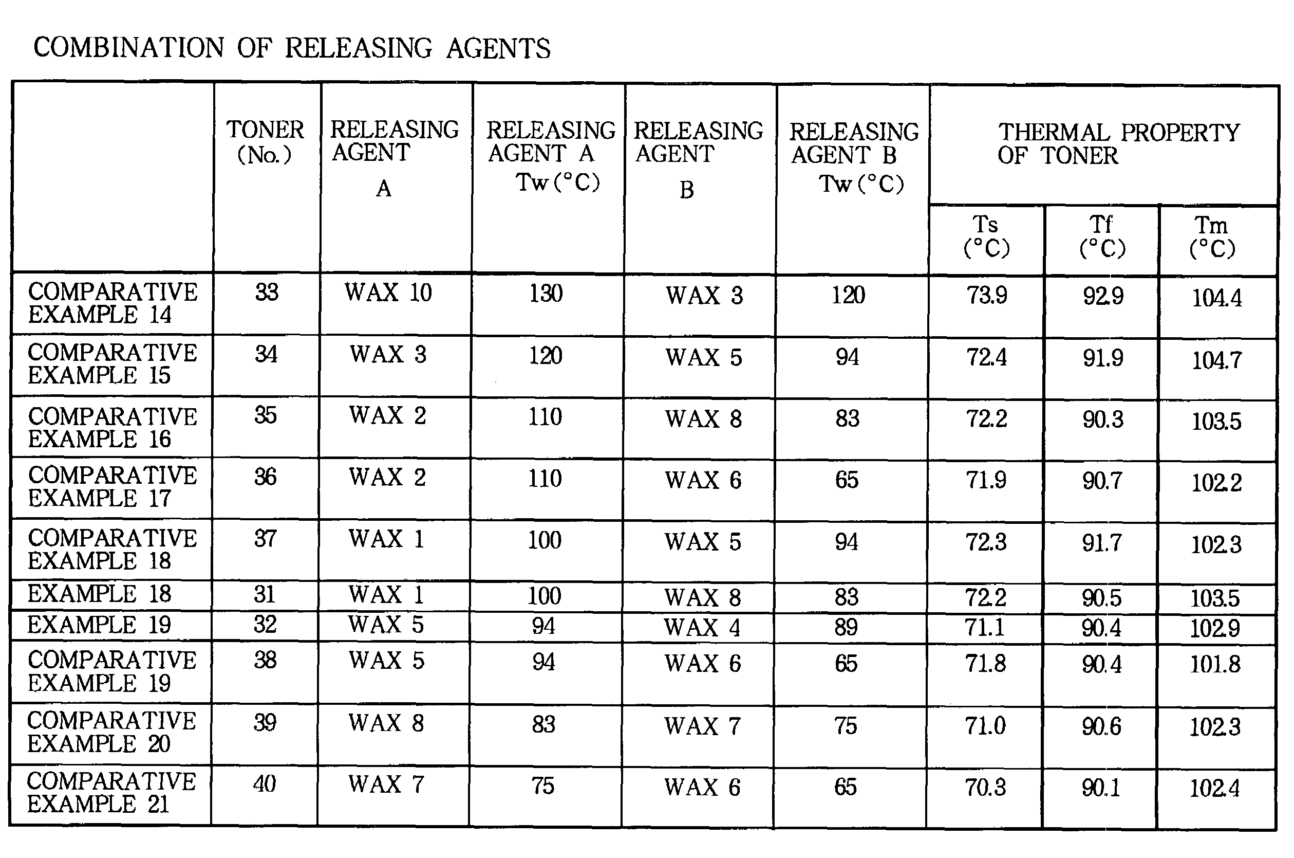
[0036]First, the toner of the first embodiment will be described. The toner of the first embodiment includes, at least, a binder resin, a releasing agent, a coloring agent, and a fluidizing agent. The melting point Tw of the releasing agent, the softening temperature Ts of the toner, and the melting temperature Tm of the toner measured by ½ method (described later) satisfy the relationship: Ts≦Tw≦Tm. Hereinafter, Examples of the toner of the first embodiment and Comparative Examples will be described.
example 1
[0037]The toner (hereinafter, referred to as toner 1) of Example 1 includes:
[0038]a binder resin (polyester resin whose number-average molecular weight Mn is 3700 and whose glass-transition temperature Tg is 62° C.) of 100 weight parts;
[0039]a charge controlling agent (salicylacetate complex) of 1.0 weight parts;
[0040]a coloring agent (phthalocyanine blue: CI pigment blue 15:3) of 3.0 weight parts, and
[0041]a releasing agent of 10.0 weight parts.
[0042]The above described compositions are sufficiently agitated and mixed in a mixing machine (“Henschel mixer” manufactured by Mitsui Miike Kakouki Co., Ltd.). The resultant material is kneaded by a continuous kneader of an open roller type (“Kneadex” manufactured by Mitsui Mining Co., Ltd.) at the temperature of 100° C. for approximately 3 hours. After the kneading, the resultant material is cooled to a room temperature. The resultant material is crushed by a crusher with an impact plate (“Dispersion Separator” manufactured by Nippon Pneu...
examples 2-5
[0056]A toner 2 of Example 2 is manufactured by replacing the wax 1 of the toner 1 with a wax 2 (whose melting point Tw2 is 110° C.) as the releasing agent. The other manufacturing condition of the toner 2 is the same as that of the toner 1.
[0057]A toner 3 of Example 3 is manufactured by replacing the wax 1 of the toner 1 with a wax 3 (whose melting point Tw3 is 120° C.) as the releasing agent. The other manufacturing condition of the toner 3 is the same as that of the toner 1.
[0058]A toner 4 of Example 2 is manufactured by replacing the wax 1 of the toner 1 with a wax 4 (whose melting point Tw4 is 89° C.) as the releasing agent. The other manufacturing condition of the toner 4 is the same as that of the toner 1.
[0059]A toner 5 of Example 5 is manufactured by replacing the wax 1 of the toner 1 with a wax 5 (whose melting point Tw5 is 94° C.) as the releasing agent. The other manufacturing condition of the toner 5 is the same as that of the toner 1.
[0060]Using the above described ton...
PUM
| Property | Measurement | Unit |
|---|---|---|
| speed | aaaaa | aaaaa |
| melting point Tw1 | aaaaa | aaaaa |
| melting point Tw2 | aaaaa | aaaaa |
Abstract
Description
Claims
Application Information
 - R&D
- Intellectual Property
- Life Sciences
- Materials
- Tech Scout
- Unparalleled Data Quality
- Higher Quality Content
- 60% Fewer Hallucinations
Browse by: Latest US Patents, China's latest patents, Technical Efficacy Thesaurus, Application Domain, Technology Topic, Popular Technical Reports.
© 2025 PatSnap. All rights reserved.Legal|Privacy policy|Modern Slavery Act Transparency Statement|Sitemap|About US| Contact US: help@patsnap.com


