Implicit-explicit switching for finite element analysis

a finite element and implicit switching technology, applied in the field of computer simulations using the finite element method, can solve the problems of inability to achieve the convergence of these iterations, and difficulty in practi

Inactive Publication Date: 2007-10-23
ANSYS
View PDF9 Cites 22 Cited by
  • Summary
  • Abstract
  • Description
  • Claims
  • Application Information

AI Technical Summary

Benefits of technology

[0025]The present invention includes a method that overcomes the disadvantages of conventional finite element simulations. The method accomplishes this by switching between an implicit method and an explicit method one or more times during a finite element simulation.

Problems solved by technology

Successful convergence of these iterations is not guaranteed and can be very difficult in practice.
A disadvantage of the implicit method is that a stiffness matrix must be formed and inverted.
Assembling and inverting the stiffness matrix in a typical application requires a relatively large amount of computer CPU and memory resources.
Another disadvantage of the implicit method is that convergence of the nonlinear equilibrium iteration process is not guaranteed.
Each simulation presents a new set of difficulties, so that reliable solutions are not always available even for expert users of the method.
A disadvantage of the explicit method is that static equilibrium can only be approximated.
Another disadvantage of the explicit method is that the Courant time step size limit requires potentially hundreds of thousands of time steps to be computed during each simulation, which significantly slows the solution process.
Yet another disadvantage of the explicit method is that techniques for accelerating the solution process, such as mass scaling, introduce artificial dynamic effects which are difficult to quantify and control.
However, simulations performed using implicit method finite element software suffer from the disadvantages of the implicit method mentioned above, and simulations performed using explicit method finite element software suffer from the disadvantages of the explicit method mentioned above.

Method used


Image

  • Implicit-explicit switching for finite element analysis
  • Implicit-explicit switching for finite element analysis
  • Implicit-explicit switching for finite element analysis

Examples


Embodiment Construction

[0040]The preferred embodiments of the present invention and their advantages are best understood by referring to FIGS. 1 through 5 of the drawings. Like numerals are used for like and corresponding parts of the various drawings.

System Overview

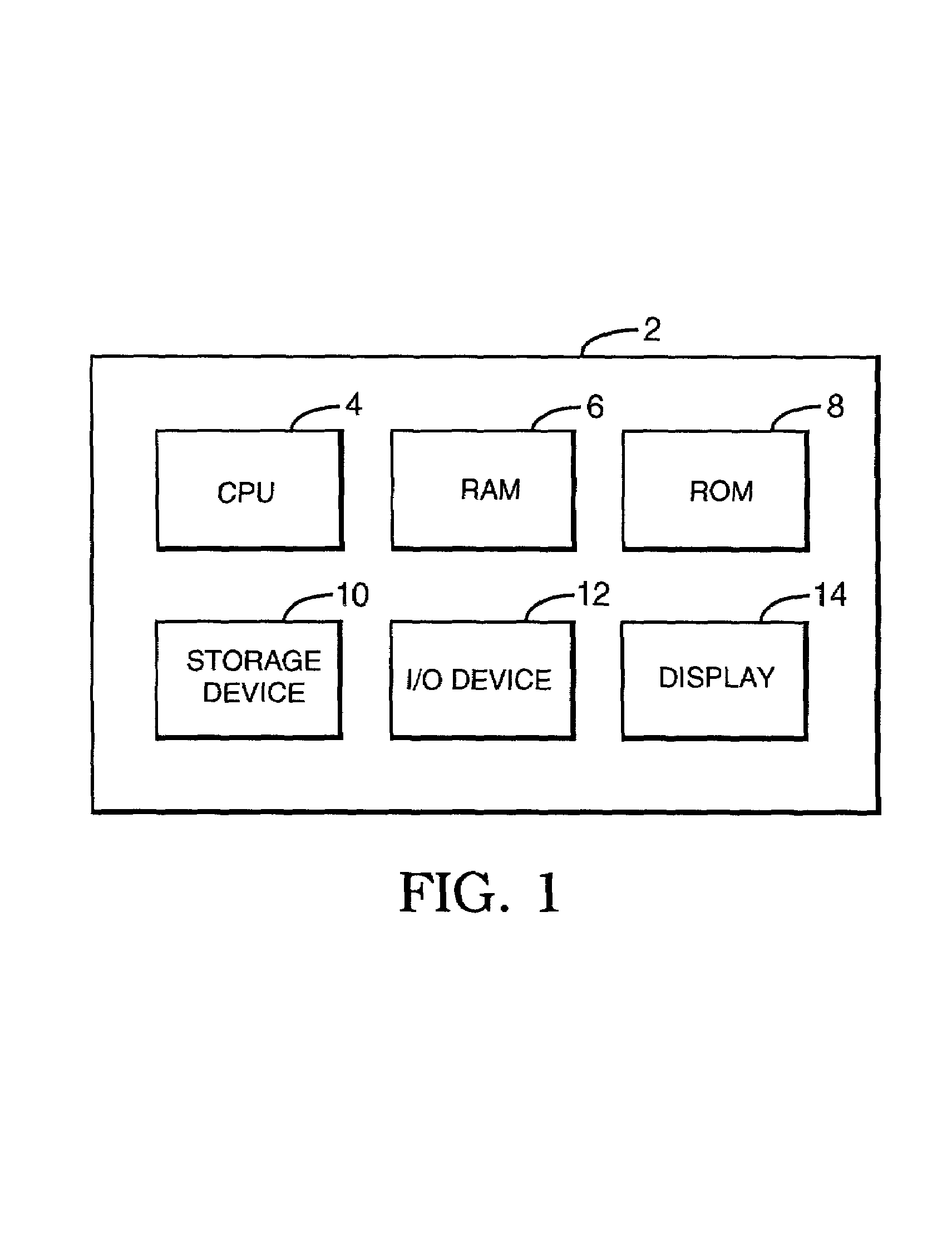
[0041]FIG. 1 is a block diagram of an exemplary computer system 2 upon which the methods of the present invention can be performed, according to an embodiment of the present invention. Computer system 2 can include one or more suitable processing facilities such as microcomputers / workstations, minicomputers, mainframes, and / or massively parallel processing computers running suitable operating systems. Examples of suitable microcomputers / workstations include the IBM PC from IBM Corporation of Armonk, N.Y., and the Sparc-Station from Sun Microsystems Corporation of Mountain View, Calif. Examples of suitable minicomputers are the VAX 750 from Digital Equipment Corporation of Maynard, Mass. and the AS / 400 from IBM. An example of a suitable mainfra...


PUM


Abstract

A method for performing a finite element simulation. The method includes switching between an implicit method and an explicit method during the finite element simulation. By switching between the implicit and explicit methods during a simulation, an accurate solution can be obtained quickly and reliably.

Description

BACKGROUND OF THE INVENTION[0001]1. Field of the Invention[0002]The present invention relates generally to computer simulations using the finite element method, and more specifically, to a method for switching between the implicit finite element method and the explicit finite element method during a simulation.[0003]2. Related Art[0004]The finite element method is a technique for obtaining approximate numerical solutions to boundary value problems which predict the response of physical systems subjected to external loads. The finite element method is described in detail by Thomas J. R. Hughes in “The Finite Element Method” (1987), published by Prentice-Hall, Inc., New Jersey, which is incorporated herein by reference in its entirety. One common use of the finite element method is in the field of solid mechanics where it is used to analyze structural problems such as the formation of stamped sheet metal parts or the springback of stamped sheet metal parts.[0005]In general, finite ele...

Claims


Application Information

Patent Timeline
Patent Type & Authority Patents(United States)
IPC IPC(8): G06G7/64G06F17/50
CPCG06F17/5018G06F30/23
Inventor MAKER, BRADLEY N.
Owner ANSYS
Why Eureka
Try Eureka