Work machine maintenance system

a technology for maintenance systems and working machines, applied in testing/monitoring control systems, instruments, wireless commuication services, etc., can solve the problems of reducing work efficiency, inconvenient for service personnel, poor maintenance efficiency, etc., to reduce work time spent on maintenance, reduce work efficiency, and easily and accurately determine which working machine is used.

Inactive Publication Date: 2007-10-23
NIHON KENKI CO LTD
View PDF14 Cites 21 Cited by
  • Summary
  • Abstract
  • Description
  • Claims
  • Application Information

AI Technical Summary

Benefits of technology

[0011]According to the maintenance system of the above working machine, it is possible to perform the series of tasks of grasping the method of approach at the time trouble arises, confirming the inventory of parts required for repair of the trouble, and, when necessary, performing the work for placing orders and thereby possible to reduce the work time spent on maintenance. When a working machine runs into trouble, this state is collected by the mounted maintenance monitor device and is automatically informed to the maintenance management server utilizing the Internet etc. The maintenance management server receiving the information relating to the occurrence of trouble stores the trouble information in a file for each working machine (each model and machine No.) and simultaneously notifies the mobile terminal of the related service personnel of the fact of the occurrence of the trouble in the working machine covered and the content of the trouble. Due to this, the service personnel can easily and accurately determine which working machine experienced what kind of trouble even without heading out to the work site. Further, in the maintenance system, the server system is divided into a maintenance management server for managing maintenance and a model information server managed by the machinery manufacturer. By having the maintenance management server operated by the machinery manufacturer, dealer, rental company, customer, etc., while having the model information server operated by the machinery manufacturer, it is possible to efficiently maintain and manage data.
[0012]The maintenance system of a working machine of the present invention further provides the above configuration where preferably the maintenance management server accesses the model information server to search through a manual database based on a request for a maintenance manual sent from a mobile terminal to the maintenance management server and the model information server acquires manual information corresponding to the request and transmits it to the mobile terminal. According to the configuration, when the service personnel has insufficient information relating to the repair of trouble, he can obtain a maintenance manual through the communicating means and does not have to bring the troubleshooting manual etc. to the work site or return to the office. Therefore, the efficiency of the maintenance work can be improved.
[0013]The maintenance system of a working machine of the present invention further provides the above configuration where preferably the model information server searches through the part inventory database and estimate database corresponding to the content of trouble, acquires inventory information of the parts for repair of trouble and estimate information for repair of trouble, and transmits them to the mobile terminal. According to this configuration, since it is possible to obtain inventory information on the parts required for repair of trouble, it is possible to immediately determine when the parts will be acquired or the repair parts and the repair date and possible to easily and quickly find the costs required for the repair. Further, it is possible to use the mobile terminal to place an order based on the inventory information.

Problems solved by technology

Depending on the content of the trouble, sometimes the service personnel could immediately repair the trouble in the site, but other times he had to make the repair while referring to a more detailed repair manual when his experience was insufficient or the trouble was complicated.
The method of service personnel heading out to the work site in which the working machine is disposed to diagnose trouble is troublesome and poor in the efficiency of the maintenance work.
Further, when the trouble cannot be immediately repaired on the site, it becomes necessary to return to the office to obtain information of more detailed repair manuals or information on inventory of replacement parts.
This is inconvenient for the service personnel and further reduces the work efficiency.
In this case, the customer cannot determine when the trouble will be fixed and cannot draw up a work schedule.
Further, there was the problem that an estimate of the costs required for repair of the trouble could not be immediately prepared.
However, this method requires that the service personnel transport the external controller to the site, connect the external controller to the body controller mounted in the working machine, and start up a troubleshooting program.
In the sense of the service personnel heading out to the site, this method had the same problem as the above-explained conventional troubleshooting method.
Also, in view of repairing the trouble the above-mentioned problems are not solved.
Managing the maintenance manuals etc. becomes troublesome and separate work is required for checking inventories or placing orders for the parts for repairing the trouble by referring to parts lists for the different models.
Accordingly, time and trouble are required for the maintenance and repair.
Even such rental companies suffer from the above problems in maintenance in the same way as the machinery manufacturers.

Method used


Image

  • Work machine maintenance system
  • Work machine maintenance system
  • Work machine maintenance system

Examples


Embodiment Construction

[0017]A preferred embodiment of the present invention will be explained below based on the attached drawings.

[0018]The configuration, shape, size, and layout explained in the embodiments are only shown in general to an extent enabling the present invention to be understood and carried out. Therefore, the present invention is not limited to the embodiment explained below and can be modified in various ways so long as the scope of the technical idea shown in the claims is not exceeded.

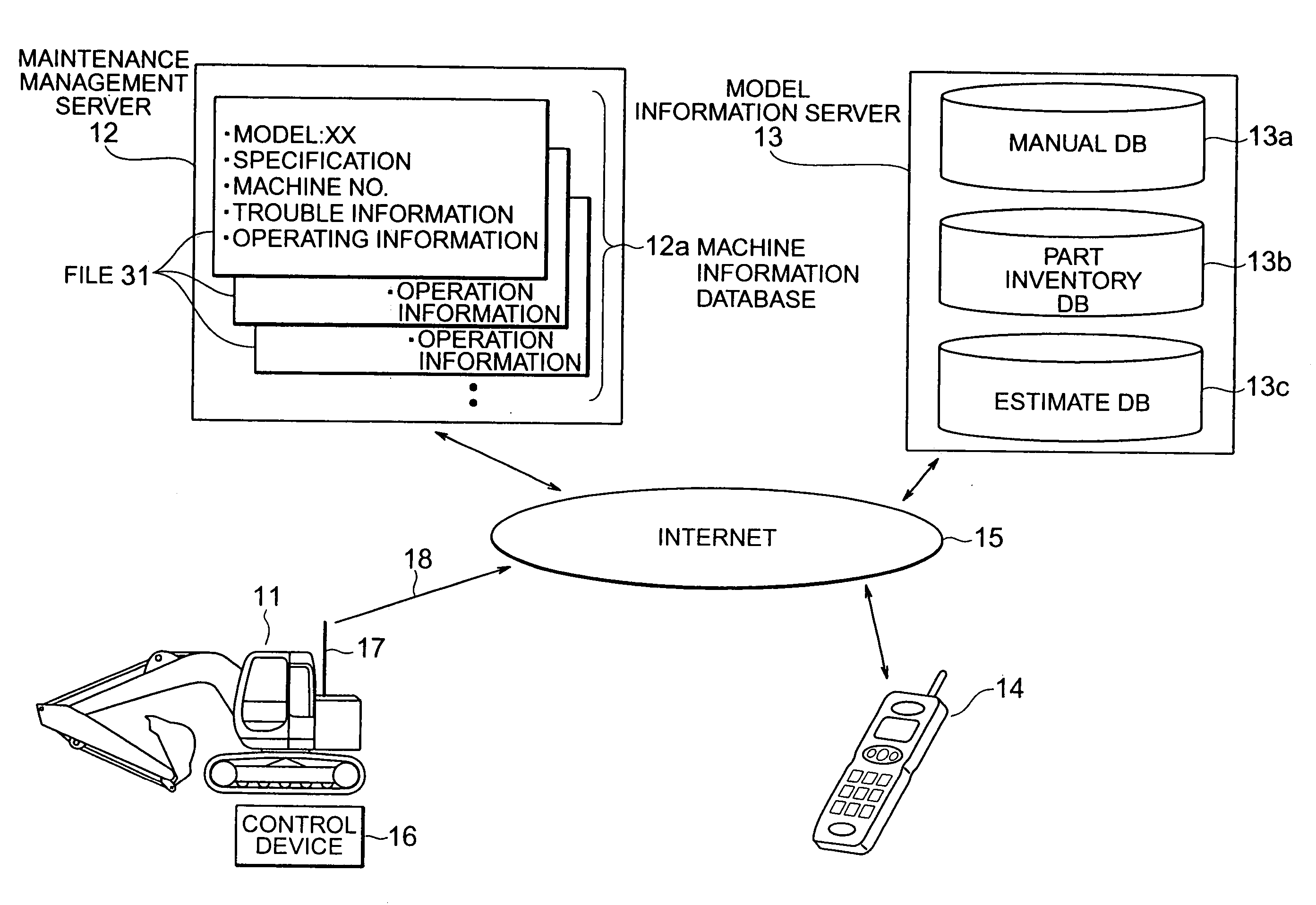
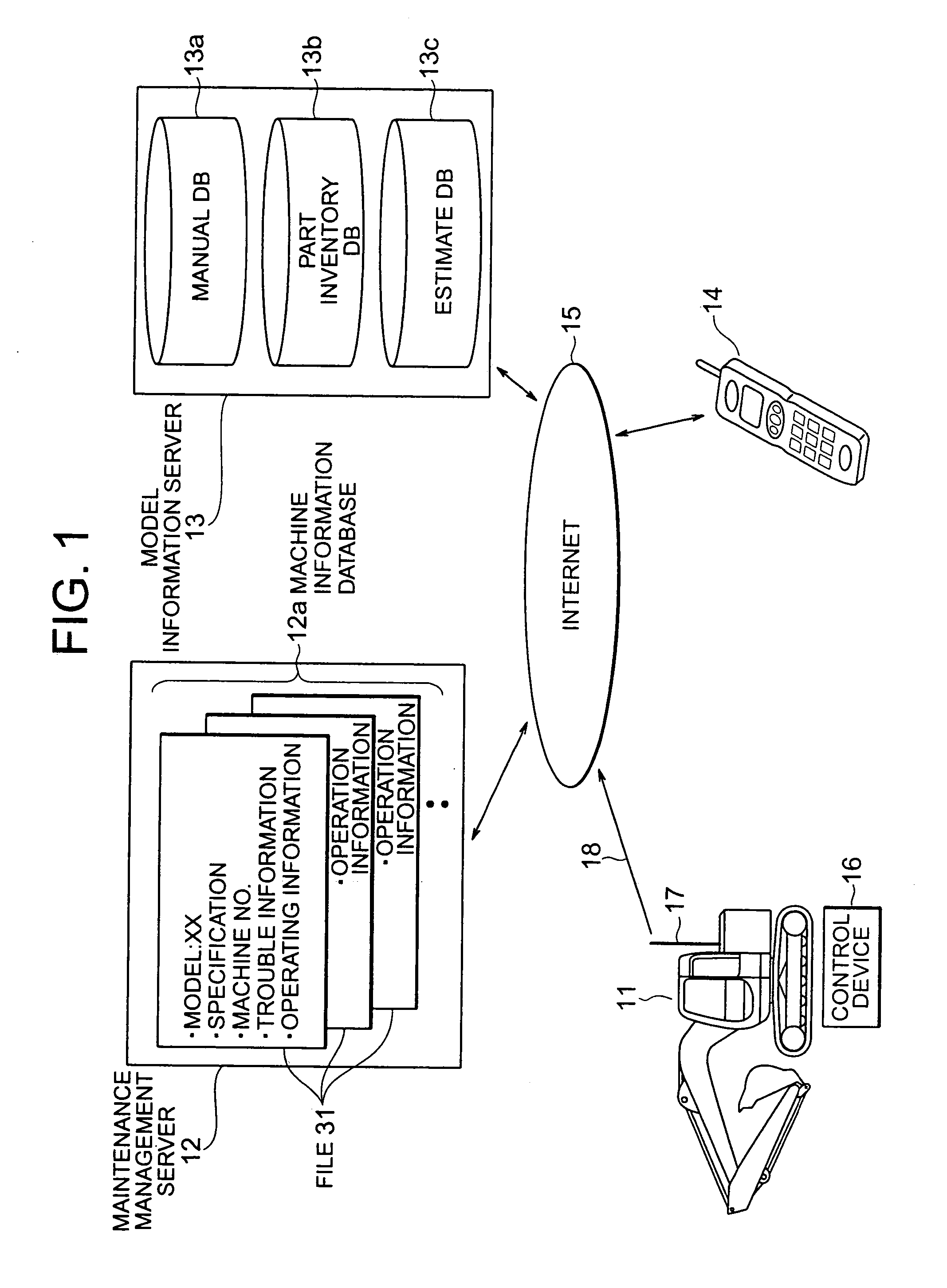
[0019]FIG. 1 shows the overall configuration of a maintenance system according to the present invention. In this embodiment, a hydraulic excavator is shown as an example of a working machine. In FIG. 1, a hydraulic excavator 11 provided at a work site, a maintenance management server 12, a model information server 13, and a mobile phone 14 are shown. These are connected through the Internet (electrical communications lines) 15 and are designed to transfer data etc. over it.

[0020]In FIG. 1, the example of...


PUM


Abstract

A maintenance system of a hydraulic excavator (11) is provided with a maintenance monitoring device (21), a maintenance management server (12) for managing trouble information and operating information for each working machine, a model information server (13), and a service personnel mobile terminal (14) connected to one another through the Internet (15). When trouble occurs in the hydraulic excavator, the maintenance system (21) transmits trouble information to the maintenance management server (12), and the maintenance management server (12) transmits information on occurrence of trouble to the mobile terminal (14) and displays it on a display unit. This system manages the maintenance manuals and other data for each model in a model information database separate from the maintenance database and correlates the two databases based on the model data.

Description

TECHNICAL FIELD[0001]The present invention relates to a maintenance system of a working machine, and more particularly, relates to a maintenance system of a working machine for monitoring troubles in an engine, hydraulic pump, hydraulic motor, operating mechanism, or parts in a hydraulic excavator, and performing unitary management on maintenance manuals, and the inventory of repair parts, etc. through a network.BACKGROUND ART[0002]Conventional fault-diagnosis or troubleshooting of a working machine disposed at a work site has usually been performed by the actions of service personnel trained in troubleshooting heading out to the site, performing work for detaching the outer panels of the working machine, running conduction checks on the various sensors and the like, then diagnosing trouble locations, and causes of trouble based on the results of the inspection and in accordance with the experience and knowledge of the service personnel while referring to a repair manual. Next, the ...

Claims


Application Information

Patent Timeline
Patent Type & Authority Patents(United States)
IPC IPC(8): G06F11/00G05B23/02G06Q10/00G06Q50/00G06Q50/08G06Q50/10H04B7/26H04W4/00H04W88/18
CPCG05B23/0272G06Q50/08
Inventor SHIBATA, KOICHIWATANABE, HIROSHISUGIYAMA, GENROKUADACHI, HIROYUKI
Owner NIHON KENKI CO LTD
Why Eureka
Try Eureka