Method and device for drilling a hole in soil or rock material and for forming an anchoring

a technology of soil or rock material and drilling method, which is applied in the direction of drilling rods, drilling pipes, drilling holes/well accessories, etc., can solve the problems of curable fluid solidification and achieve the effect of increasing the outer diameter

Inactive Publication Date: 2007-10-30
ALWAG TUNNELAUSBAU GMBH
View PDF4 Cites 7 Cited by
  • Summary
  • Abstract
  • Description
  • Claims
  • Application Information

AI Technical Summary

Benefits of technology

[0007]For the introduction of large forces, which are provided in a manner uniformly distributed over the cross section of the borehole, it is contemplated according to a further preferred embodiment that, in a manner known per se, the tension elements are comprised of a plurality of wires or ropes substantially radially surrounding the drill rod assembly and mounted in a non-rotational manner relative to the borehole wall during the drilling of the borehole. By an appropriate number of wires or ropes arranged substantially radially around the drill rod assembly to form the tension elements, a uniform force introduction is subsequently ensured by the tension elements and the introduction of the tension elements can, moreover, be reliably effected during the drilling procedure. In doing so, it is provided according to the invention that despite a rotational movement to be optionally provided of the drill bit and, hence, the drill rod assembly, the tension elements are mounted in a non-rotational manner relative to the borehole wall in order to avoid any distortion or twist of the tension elements about the borehole axis defined by the drill rod assembly during the drilling procedure while, at the same time, shortening the effective lengths of the tension elements.
[0012]To solve the objects mentioned in the beginning, a device of the above-identified type is, moreover, essentially characterized in that anchoring or fixing elements for anchoring to the borehole inner wall are provided on the drill bit, on its end facing away from the working face, and / or on the tension elements, and that the tension elements, for tensioning or centering, are capable of being subjected to a distortion or twist while shortening their effective lengths, on their ends projecting out of the borehole. It is, thus, feasible to reliably secure the drill bit and / or the tension elements, particularly on their ends facing the borehole interior, so as to enable the subsequent centering and / or at least temporary or provisional tensioning of the tension elements prior to the solidification of the curable material. Such shortening of the effective lengths of the tension elements in a particularly simple manner can be realized by a distortion or twist of the same so as to provide a proper distribution of the tension elements over the cross section of the borehole and ensure the uniform introduction and absorption of force.
[0013]For a uniform distribution of the forces to be introduced or absorbed, it is, moreover, proposed in a preferred manner that the tension elements, in a manner known per se, are comprised of a plurality of wires or ropes substantially radially surrounding the drill rod assembly and mounted on the drill bit in a non-rotational manner relative to the borehole wall during the formation of the borehole. By mounting the tension elements on the drill bit in a non-rotational manner relative to the borehole wall during their introduction, a reliable introduction will, moreover, be ensured.
[0014]For the reliable entrainment of the tension elements during the drilling procedure, it is provided according to a further preferred embodiment that, on the drill bit end facing away from the working face, a sleeve-shaped element is mounted on the drill bit or an, impact shoe cooperating therewith, with the tension elements being fixed to the sleeve-shaped element.
[0016]A structurally simple and reliable fixation of the tension elements via the sleeve-shaped element and a reliable expansion during centering or tensioning will, moreover, be ensured in that the sleeve-shaped element is secured to the drill bit, or an impact shoe cooperating therewith, in a fixation region extending from the working face of the drill bit and having an increasing outer diameter, as in correspondence with a further preferred embodiment of the device according to the invention.
[0017]For the reliable and proper securement or fixation of the device, particularly on the end facing the interior of the borehole, it is provided according to a further preferred embodiment that the fixing elements are comprised of at least one hook or the like, in particular foldout hook, projecting from the outer periphery of the drill bit and / or sleeve-shaped element. Such hooks will penetrate into the surrounding rock or soil material and, hence, provide securement during the tensioning of the jacket tube. By arranging the pivot axes of the hooks, in particular, on hook ends facing the borehole interior, the substantially automatic emergence of the hooks will be caused by a retraction of the device or tension elements during tensioning such that no additional and optionally expensive mechanisms for bringing out or extracting the fixing or anchoring elements will be required.

Problems solved by technology

Those known configurations involved the drawback that the solidification of the curable fluid had to be awaited for the tensioning and centering of the tension elements, since the tension elements would have been immediately pulled out of, and removed from, the borehole, if the tension elements had been tensioned prior to the solidification of the curable fluid, since no anchorage or securement of the tension elements was provided prior to said solidification.

Method used


Image

  • Method and device for drilling a hole in soil or rock material and for forming an anchoring
  • Method and device for drilling a hole in soil or rock material and for forming an anchoring
  • Method and device for drilling a hole in soil or rock material and for forming an anchoring

Examples


Embodiment Construction

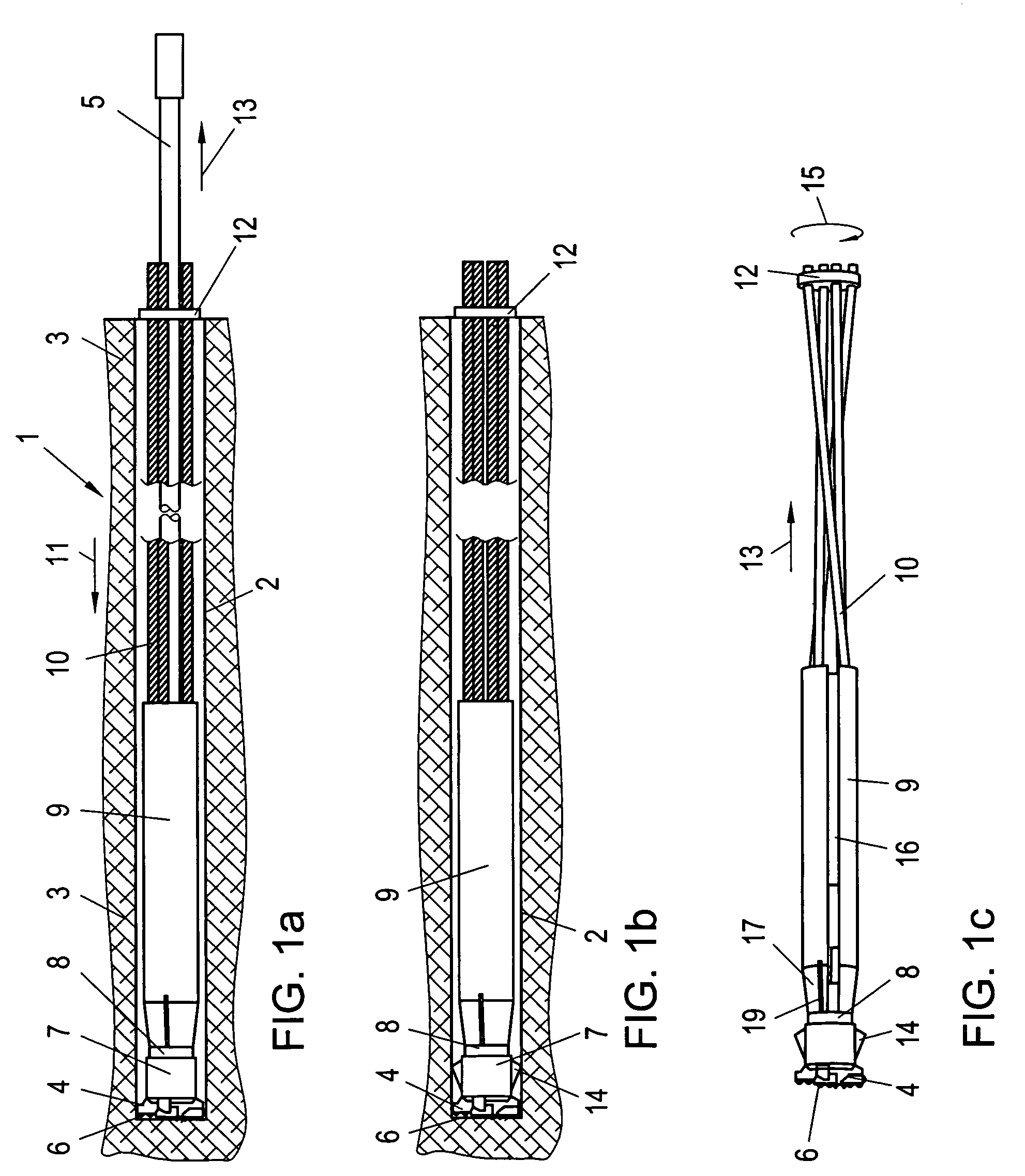
[0023]FIGS. 1a-1c depict different steps in the production of a borehole using a device generally denoted by 1, for the drilling, in particular percussion drilling or rotary percussion drilling, of a hole 2 in soil or rock material schematically indicated by 3.

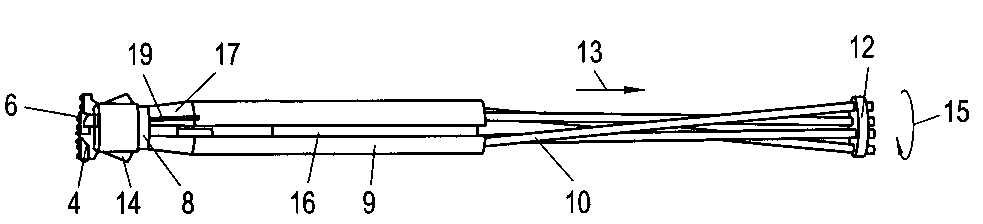
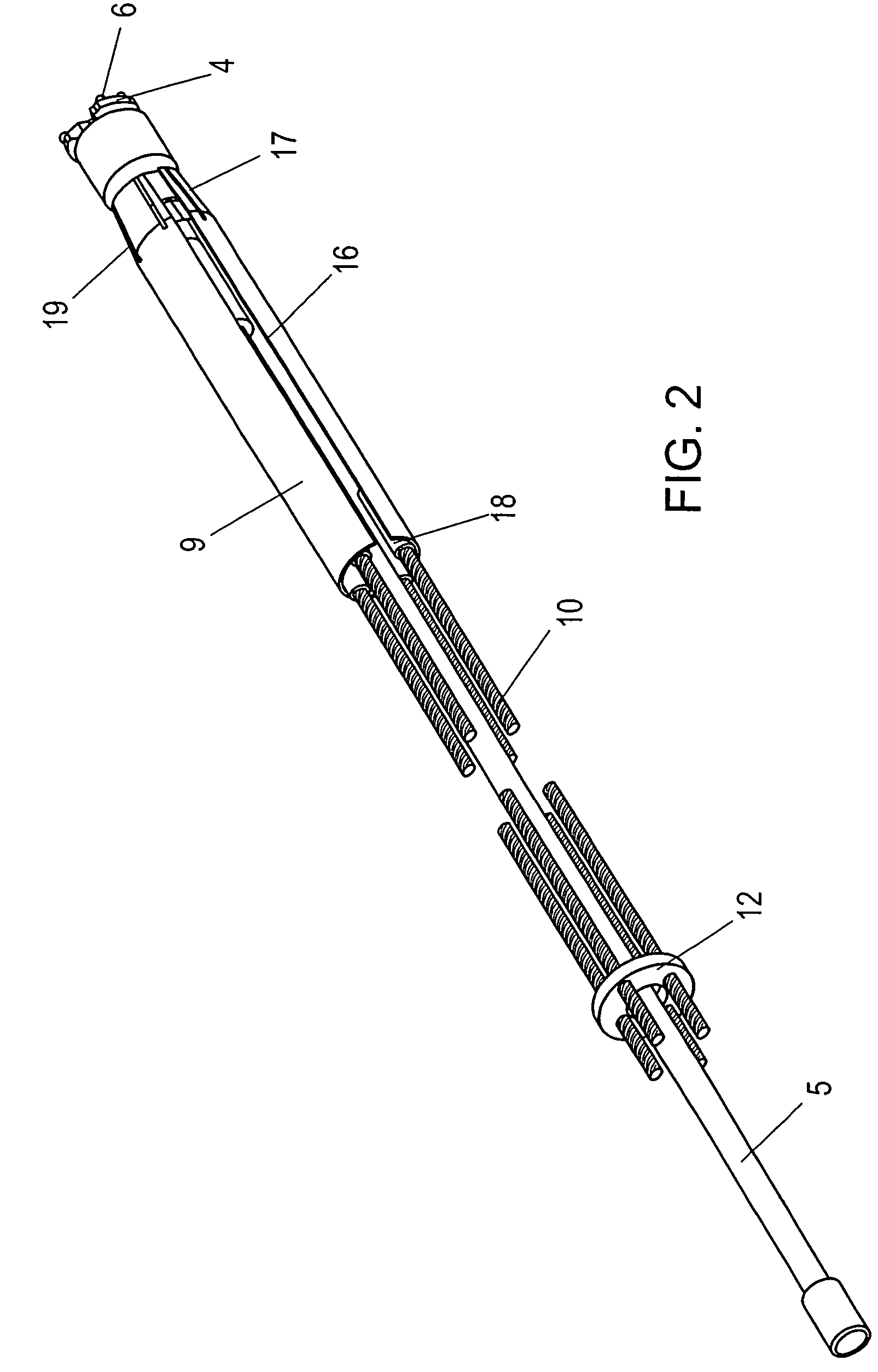
[0024]In the illustrations according to FIGS. 1a-1c and 2, a schematically indicated drill bit 4 is provided, which is set in a percussive and / or rotary percussive movement by a drive not illustrated in detail, via a drill rod assembly denoted by 5 in FIG. 1a, in order to form a borehole 2 with excavation elements 6 indicated on the drill bit 4.

[0025]An impact shoe 8, which is more clearly apparent especially from FIG. 3, follows upon the drill bit 4 via an intermediate element 7, which will be explained in more detail below and, in particular, with reference to FIGS. 3 and 4a-4c, wherein a sleeve-shaped element 9 is mounted on the impact shoe 8 to secure and entrain, during the drilling procedure, tension elements 10 formed, ...


PUM


Abstract

A method and device for boring a hole in soil or rock material and for forming an anchoring are disclosed. A borehole is formed by inserting a drill bit, and tensioning elements coupled to the drill bit are introduced into the borehole. After completion, the boring rods are detached from the drill bit and removed. The boring rods are provided with a hollow space in its longitudinal direction to introduce a hardenable fluid into the borehole. Anchoring or fixing elements for anchoring on the borehole's inner wall are provided on the drill bit at the end opposite the drilling surface and / or on the tensioning elements. The tensioning elements are subjected to a turning or twisting whereby shortening their effective length for tensioning or centering so that a centering and an optionally temporary tensioning of the tensioning elements can be effected before the hardenable material completely hardens.

Description

[0001]This is a continuation of PCT / AT05 / 000100 filed Mar. 22, 2005 and published in German.FIELD OF THE INVENTION[0002]The present invention relates to a method for drilling, in particular percussion drilling or rotary percussion drilling, a hole in soil or rock material and for forming an anchoring in said hole, wherein a borehole is formed by the introduction of a drill bit mounted on a drill rod assembly and tensioning elements coupled to the drill bit are introduced into the borehole during the drilling procedure, wherein the drill rod assembly is detached from the drill bit and removed from the borehole upon completion of the borehole, and wherein, during the removal of the drill rod assembly from the borehole, a curable fluid is introduced into the borehole through a hollow space provided in the drill rod assembly. The present invention further relates to a device for drilling, in particular percussion drilling or rotary percussion drilling, a hole in soil or rock material an...

Claims


Application Information

Patent Timeline
Patent Type & Authority Patents(United States)
IPC IPC(8): E21B17/10E21D20/00E02D5/76E02D5/80
CPCE02D5/808E02D5/76
Inventor MOCIVNIK, JOSEFEGGER-MOCIVNIK, RENE
Owner ALWAG TUNNELAUSBAU GMBH
Why Eureka
Try Eureka