Backlight assembly and display device having the same

a backlight assembly and display device technology, applied in the field of backlight assembly, can solve the problems of increasing the manufacturing cost and achieve the effect of reducing the size of the backlight assembly

Active Publication Date: 2007-10-30
SAMSUNG DISPLAY CO LTD
View PDF6 Cites 48 Cited by
  • Summary
  • Abstract
  • Description
  • Claims
  • Application Information

AI Technical Summary

Benefits of technology

[0010]Embodiments of the present invention provide a backlight assembly capable of uniformizing an optical distribution and reducing a thickness, and a display device having the backlight assembly.
[0018]A light source unit is disposed in a groove that is formed on a lower face of a tight guiding plate, thereby uniformizing an optical distribution of a backlight assembly having the light guiding plate and reducing a size of the backlight assembly. Also, an optical path changing pattern is formed on a portion of an upper face of the light guiding plate corresponding to the light source unit, thereby further uniformizing the optical distribution.

Problems solved by technology

However, since conventional LEDs are expensive, manufacturing costs of the backlight assembly have increased.

Method used


Image

  • Backlight assembly and display device having the same
  • Backlight assembly and display device having the same
  • Backlight assembly and display device having the same

Examples


Embodiment Construction

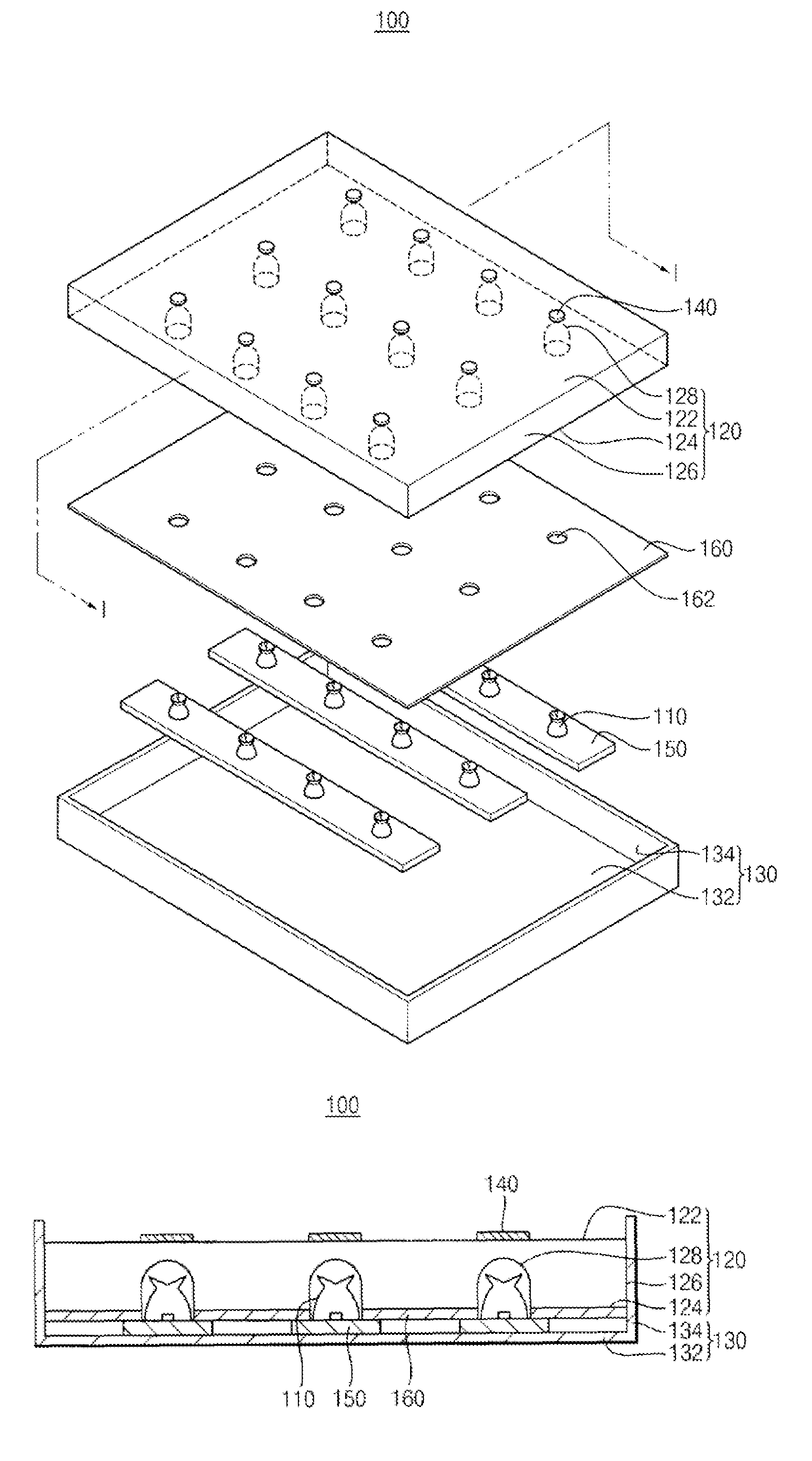
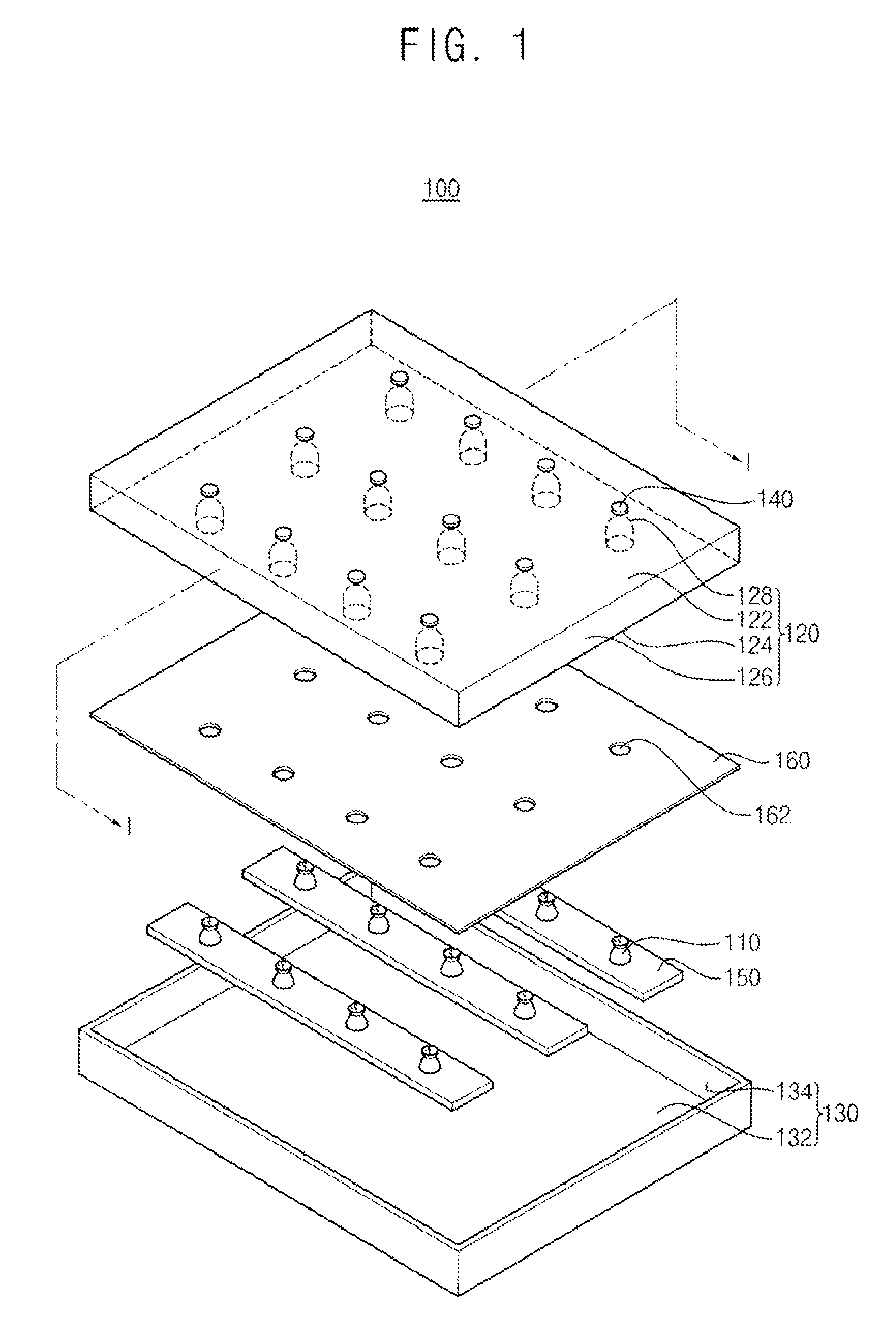
[0032]Exemplary embodiments of the present invention will be described more fully hereinafter with reference to the accompanying drawings. This invention may, however, be embodied in many different forms and should not be construed as limited to the embodiments set forth here n. It will be understood that when an element is referred to as being “on” or “onto” another element, it may be directly on the other element or intervening elements may also be present. FIG. 1 is an exploded perspective view illustrating a backlight assembly according to an exemplary embodiment of the present invention, FIG. 2 is a cross-sectional view taken along a line I-I′ in FIG. 1.

[0033]Referring to FIGS. 1 and 2, a backlight assembly 100 includes a plurality of light source units 110, a light guiding plate 120 and a receiving container 130.

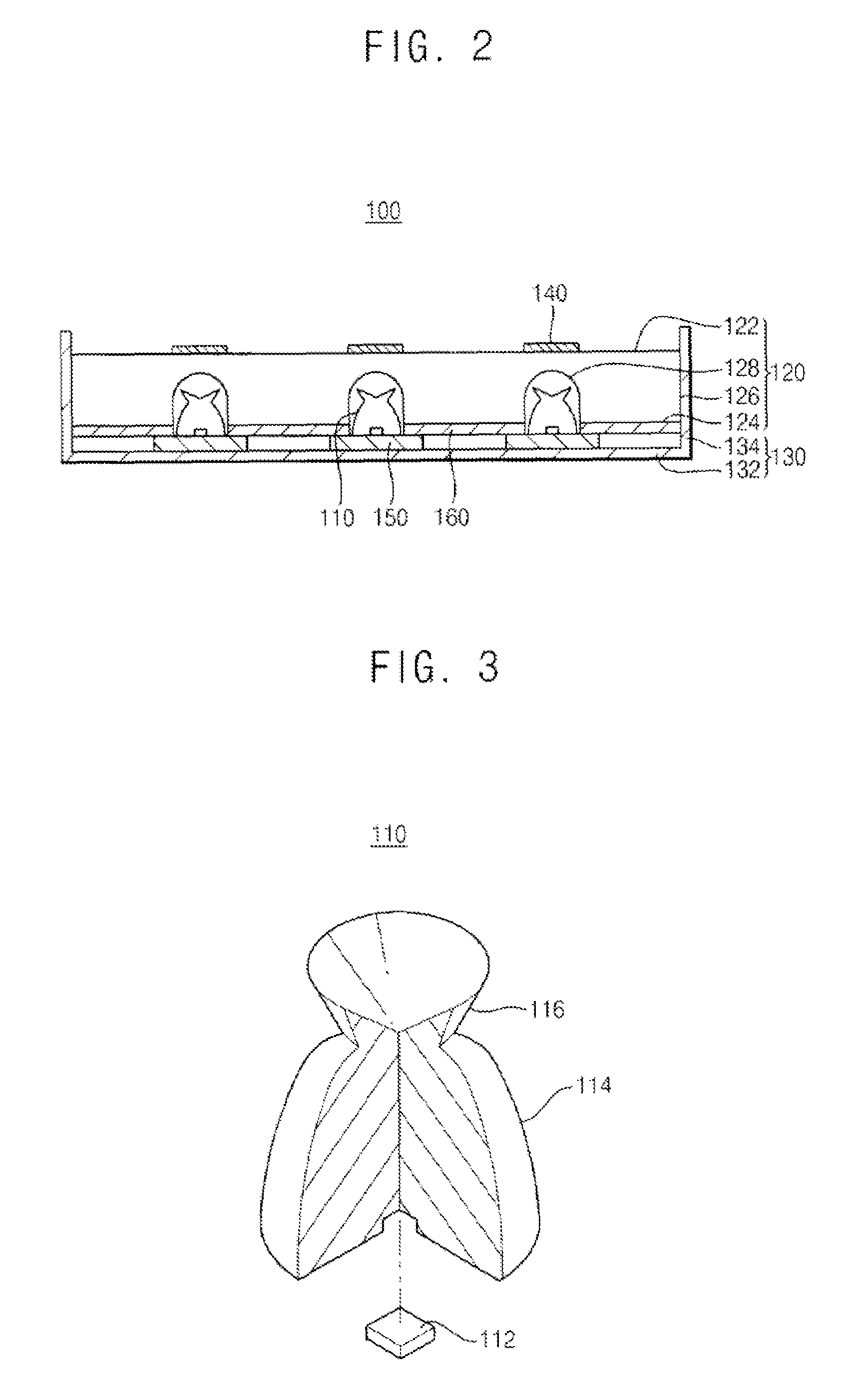
[0034]The light source units 110 are arranged in a matrix shape, and each of the light source units 110 serves as a point light source.

[0035]In FIGS. 1 and 2, each of ...


PUM


Abstract

A backlight assembly includes a light source unit a light guiding plate and an optical changing pattern. The tight source unit includes a light source, a first lens portion enclosing the light source and a second lens portion positioned on the first lens portion. The second lens portion has a concave shape at an upper face. The light guiding plate includes an upper face and a lower face. The light guiding plate has a groove formed on the lower face to enclose at least a portion of the light source unit. The light guiding plate guides the light generated from the light source unit. The optical path changing pattern is formed on the upper face of the light guiding plate, and faces the light source unit. As a result, an optical distribution of the backlight assembly may be uniformized, and a size of the backlight assembly may be reduced.

Description

CROSS-REFERENCE TO RELATED APPLICATIONS[0001]This application claims priority to Korean Patent Application No. 2006-11058 filed on Feb. 6, 2006, the contents of which are herein incorporated by reference in their entireties.BACKGROUND OF THE INVENTION[0002]1. Technical Field[0003]The present invention relates to a backlight assembly and, more particularly, to a backlight assembly capable of improving optical characteristics and a display device having the backlight assembly.[0004]2. Discussion of the Related Art[0005]A display device can convert electrical format data from an information processing unit into a visible image to display the image. Examples of the display device include a cathode ray tube (CRT) type display device, a plasma display panel (PDP) device, a liquid crystal display (LCOD) device, and an electroluminescence (EL) display device.[0006]The LCD device, a type of flat panel display device, displays an image using electrical characteristics and optical characterist...

Claims


Application Information

Patent Timeline
Patent Type & Authority Patents(United States)
IPC IPC(8): F21V8/00
CPCG02F1/133603G02B19/0028G02B19/0066G02B19/0071G02F1/133606G02F1/133611H01L33/58C02F1/66B01D39/2068F16K31/18
Inventor PARK, SE-KINAM, SEOK-HYUNYANG, BYUNG-CHOON
Owner SAMSUNG DISPLAY CO LTD
Why Eureka
Try Eureka