System for injecting a by-pass fluid in a separation method in a simulated moving bed

Inactive Publication Date: 2007-10-30
INST FR DU PETROLE
View PDF14 Cites 27 Cited by
  • Summary
  • Abstract
  • Description
  • Claims
  • Application Information

AI Technical Summary

Benefits of technology

[0025]In case of debottlenecking operations in a unit in order to replace the molecular sieve and/or to mechanically reinforce the distribution plates. When this type of modification is required, it involves changing the existing rotary valve. A configuration change requires replacement of the rotor o

Problems solved by technology

1) when each plate is equipped with at least two independent distribution networks (D1 and D2), network D1 of plate P is for example communicated with network D2 of plate P+1, and network D1 of plate P+1 is communicated with network D2 of plate P+2, so as to have a permanent fluid circulation in all the distribution networks on each distribution plate, and, for each plate, a diverted fluid stream flows from a distribution network to the main fluid and a second diverted fluid stream, substantially similar, flows from the main fluid to the second distribution network. The driving force of these flows is provided by the pressure drop caused by the main fluid flowing in the porous granu

Method used


Image

  • System for injecting a by-pass fluid in a separation method in a simulated moving bed
  • System for injecting a by-pass fluid in a separation method in a simulated moving bed
  • System for injecting a by-pass fluid in a separation method in a simulated moving bed

Examples


first embodiment

VARIANT

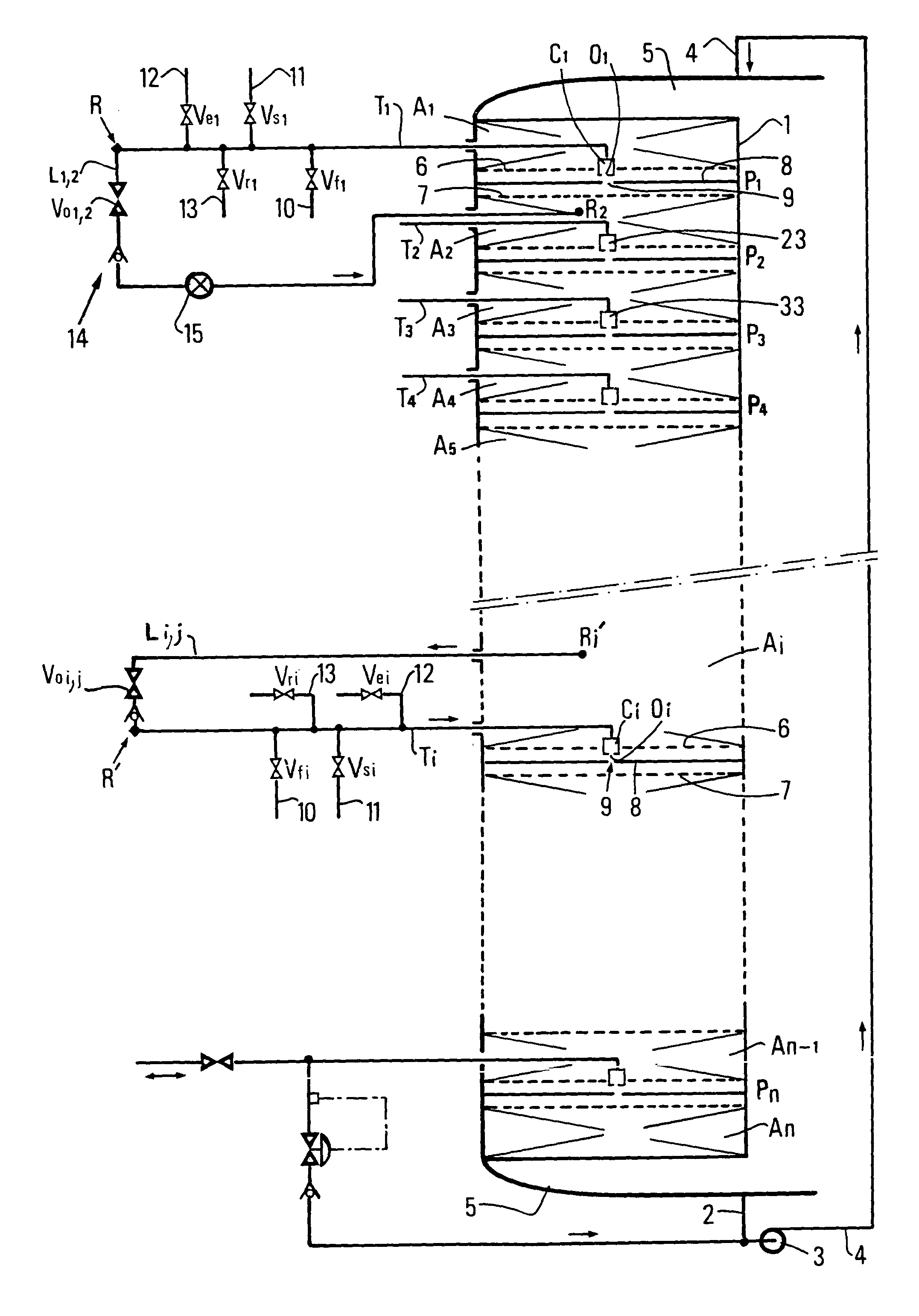
[0090]In the variant shown in the upper part of FIG. 1, a first end of line L1,2 intended for diversion of the fluid between plate P1 and plate P2 is connected by a connection point R to fluid delivery and / or extraction line T1 which communicates with chamber C1 and the second end of line L1,2 is connected by suitable means, some examples of which are given hereafter, to a zone R2 of the next adsorbent bed A2. Such a layout allows to draw off a fraction of the main fluid from bed A1 situated downstream from plate P1, to extract it through line T1 and to reinject it into adsorbent bed A2 via bypass line L1,2 in zone R2. The function of the fraction drawn off is to flush the bypass line and the distribution spider of the plate of bed A1 located immediately downstream.

[0091]A sequence cycle of the separation process implemented according to the first embodiment variant can comprise the following stages for example:

1) injection of the feed into chamber Ci,

2) diversion of the flui...

second embodiment

VARIANT

[0093]In the variant shown in the lower part of FIG. 1, a first end of bypass line Li,j is connected to an adsorbent bed Ai, for example in a zone R′i, by suitable means, and the second end of this line is connected by a point R′ to secondary fluid delivery and extraction line Ti. This variant allows to draw off, from the adsorbent bed, part of the main fluid in order to reinject it into a distribution chamber of the plate situated downstream from the draw-off point.

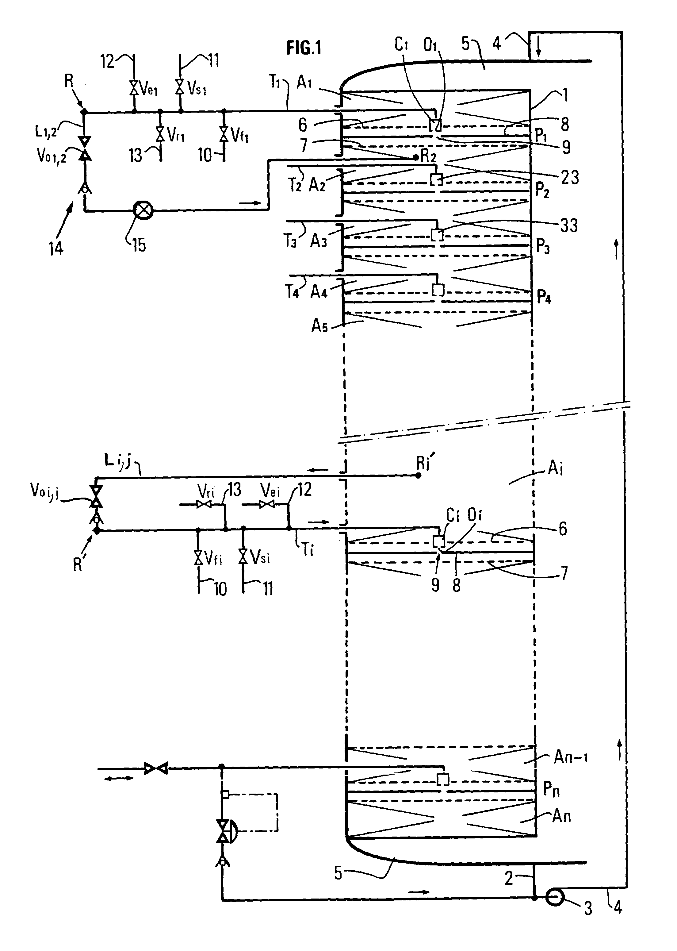
[0094]FIGS. 2A and 2B diagrammatically show another variant which differs from FIG. 1 in the secondary fluid delivery and extraction circuit.

[0095]For these two variants, the circuit comprises a rotary valve 20 whose function is to communicate the various distribution, extraction and draw-off chambers Ci with fluid sources or lines situated outside the column and also to fulfil the fluid diversion function.

[0096]Four secondary fluid transfer lines (10, 11, 12, 13) similar to those shown in FIG. 1 are connected to ...


PUM

PropertyMeasurementUnit
Fractionaaaaaaaaaa
Timeaaaaaaaaaa
Thicknessaaaaaaaaaa

Abstract

Device and process for separating at least one compound from a mixture in a simulated moving bed, comprising:
    • an enclosure comprising several absorbent beds, two adsorbent beds being separated by a fluid distribution and extraction plate (Pi), the plate comprising one or more distribution, mixing and/or extracting panels, comprising a chamber (Ci),
    • main fluid delivery (4) and extraction (2) lines,
    • several secondary fluid extraction or injection lines (10, 11, 12, 13, Ti),
    • a bypass circuit communicating a distribution plate with a bypass line,
    • means (14, Voi,j, 20) communicating at least one chamber (Ci) with at least one bypass line (Li,j),
    • at least one of the ends of a bypass line communicates with a zone Ri, R′I of an adsorbent bed, said zone being distinct from a distribution chamber (Ci) and another end is connected to said chamber (Ci).

Description

REFERENCE TO RELATED APPLICATIONS[0001]This application is a 371 of PCT / FR00 / 01455 filed May 26, 2000.FIELD OF THE INVENTION[0002]The present invention relates to a device for injecting a fluid stream used as a diverted fluid in a separation process using several adsorbent beds, a main fluid stream and several secondary fluids, the beds being separated by at least one fluid distribution plate, the plate can comprise one or more distributor mixer extractor panels allowing to inject and / or to mix and / or to extract one or more secondary fluids by means of a single distribution chamber.[0003]The invention notably applies to the device and to the process described in the claimant's patent application FR-2,772,634 when injection and extraction of secondary fluids are performed by means of a single distribution network commonly referred to as distribution <<spider>>.[0004]The invention also relates to all the processes where it is desired to improve the purity of at least one c...

Claims


Application Information

Patent Timeline
IPC IPC(8): B01D15/08B01D15/02B01D15/18C07C7/12
CPCB01D15/02B01D15/1842C07C7/12C07C15/08
Inventor HOTIER, GERARDDECOODT, XAVIERFERSCHNEIDER, GILLESVIGUIE, JEAN-CHRISTOPHE
Owner INST FR DU PETROLE
Why Eureka
Try Eureka