Electronic package and packaging method

a technology of electronic packaging and packaging methods, applied in the field of electronic packaging, can solve the problems of warping of electronic packaging, none of those techniques, etc., and achieve the effects of reducing the size of electronic packaging, reducing the amount of stress, and high reliability

Inactive Publication Date: 2007-10-30
CITIZEN ELECTRONICS CO LTD
View PDF8 Cites 6 Cited by
  • Summary
  • Abstract
  • Description
  • Claims
  • Application Information

AI Technical Summary

Benefits of technology

[0021]As thus far explained, the present invention can reduce the size of the electronic package. The electronic package has two substrates, that is, upper and lower substrates. The two substrates cooperate together to retard expansion of the encapsulating medium which may occur when the substrates are heated to high temperatures, for example, in a reflow oven. In other words, the two substrates can reduce the amount of stress exerted on the electronic component(s). The present invention can thus provide a highly reliable and reduced-size electronic component.

Problems solved by technology

None of those techniques, however, meets the above need to reduce the size of the electronic package.
The electronic package is also subject to warping, for example, during being mounted on the substrate of a cell phone and heated to a high temperature within a reflow oven.

Method used


Image

  • Electronic package and packaging method
  • Electronic package and packaging method
  • Electronic package and packaging method

Examples


Embodiment Construction

[0034]The present invention will now be described with reference to the accompanying drawings.

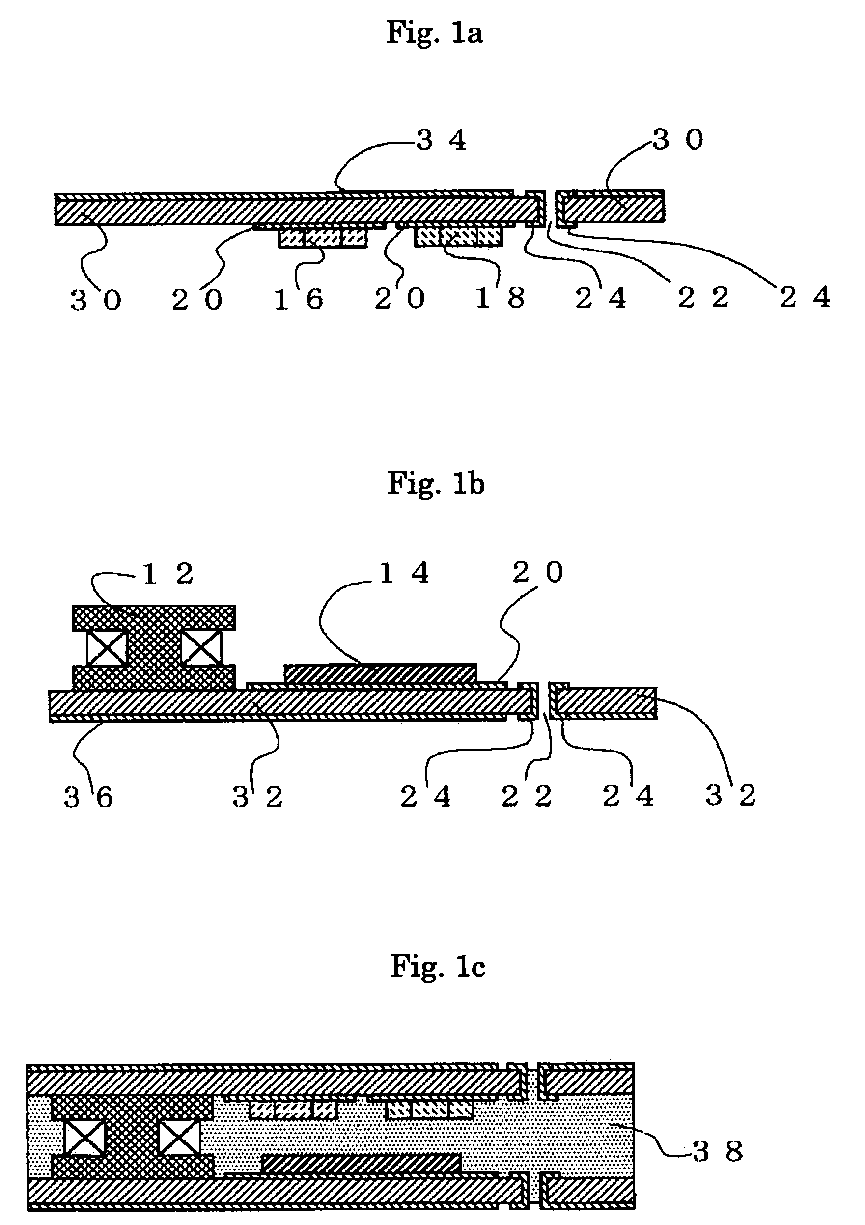
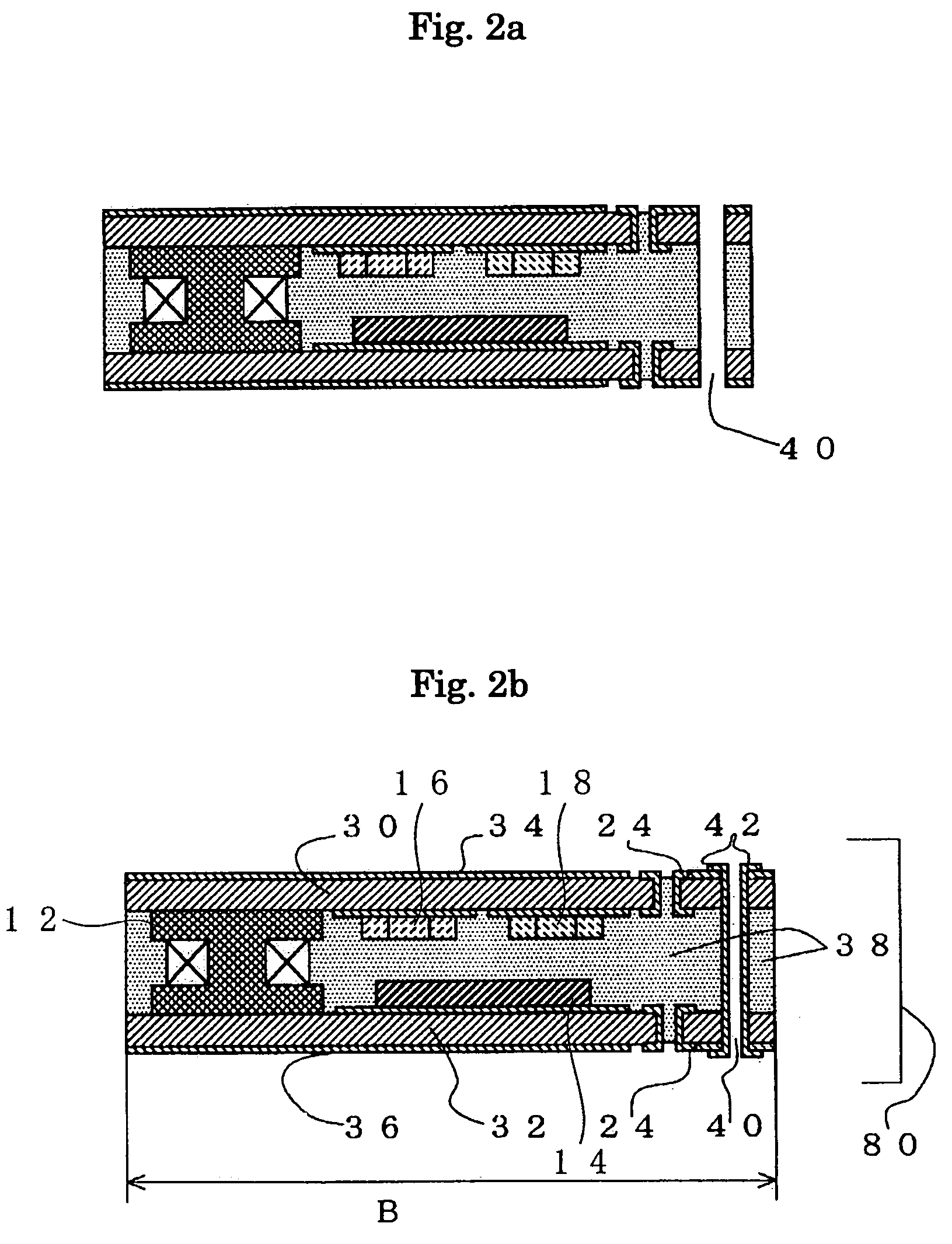
[0035]FIG. 1a through FIG. 2b show a method for fabricating an electronic package 80 (see FIG. 2b) according to the present invention.

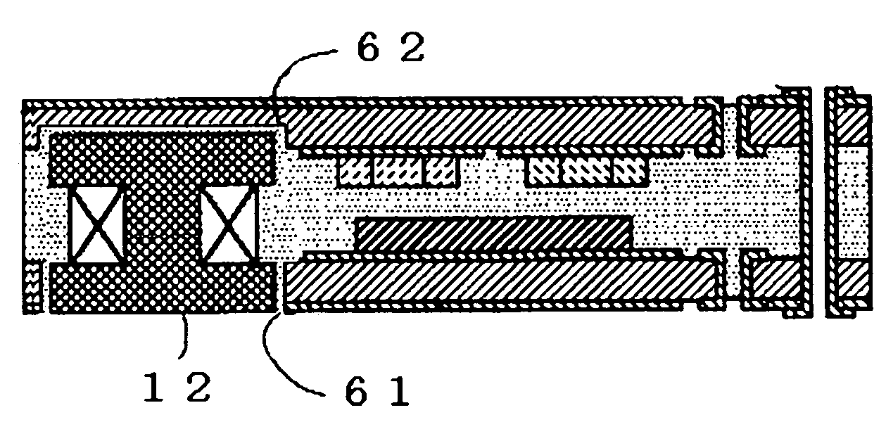
[0036]As shown, the electronic package 80 includes a first and second substrate 30, 32 extending parallel to each other, a plurality of electronic components such as a coil assembly 12, an integrated circuit 14, capacitors 16 and resistors 18, and an encapsulating resin 38 provided between the first substrate 30 and the second substrate 32 to encapsulate the electronic components.

[0037]As shown in FIG. 1a, the first substrate 30 has front and back surfaces (lower and upper surfaces as seen in FIG. 1a). A wiring metal film 20 and a wiring metal film 34 are disposed on the front and back surfaces, respectively. The capacitors 16, the resistors 18 are surface-mounted on the front surface of the first substrate 30. The first substrate 30 includes vias. Each of th...


PUM


Abstract

A first substrate includes a coil assembly and an integrated circuit mounted thereon. A second substrate includes capacitors 16 and resistors mounted thereon. The first substrate and the second substrate are interconnected by an encapsulating medium. A conductive via is provided to electrically connect the first substrate and the second substrate together

Description

[0001]This application claims priority under 35 U.S.C. §119 to Japanese Patent Application No. 2005-014921 filed Jan. 24, 2005, the entire content of which is hereby incorporated by reference.FIELD OF THE INVENTION[0002]The present invention relates to electronic packages and a method for fabricating electronic packages.BACKGROUND OF THE INVENTION[0003]Conventionally, to fabricate an electronic package particularly for use in an electroluminecent driver with a coil assembly, an integrated circuit, a coil assembly, capacitors, resistors and other electronic components are first mounted on a wafer. The electronic components are then encapsulated by an encapsulating epoxy resin. After the epoxy resin is cured, the wafer is diced to individual packages. FIGS. 7a and 7b are a sectional and plan view of such a conventional electronic package.[0004]Specifically, the electronic package includes a substrate 10. A coil assembly 12, an integrated circuit 14, capacitors 16 and resistors 18 are ...

Claims


Application Information

Patent Timeline
Patent Type & Authority Patents(United States)
IPC IPC(8): H01L23/28
CPCH05K1/186H05K3/4623H05K2201/09536H05K2201/1003H01L2924/0002H01L2924/00
Inventor KOIKE, TETSUYA
Owner CITIZEN ELECTRONICS CO LTD
Why Eureka
Try Eureka