Power control circuit for accurate control of power amplifier output power

a power amplifier and power control circuit technology, applied in the direction of supply voltage varying control, gain control, transmission, etc., can solve the problems of increasing cost and circuit design complexity, significant variations in power delivered to the load, and current techniques for controlling so as to accurately control the output power of a power amplifier. , the effect of accurate control of the output power of the power amplifier

Active Publication Date: 2007-10-30
SKYWORKS SOLUTIONS INC
View PDF13 Cites 19 Cited by
  • Summary
  • Abstract
  • Description
  • Claims
  • Application Information

AI Technical Summary

Problems solved by technology

However, current techniques for controlling the output power of a power amplifier suffer various disadvantages.
For example, techniques that indirectly control the output power by controlling the voltage or current, such as collector voltage or collector current, supplied to the power amplifier provide adequate compensation for variations in operating conditions, but undesirably allow significant variations in power delivered to the load.
However, this approach requires radio frequency (RF) circuitry for detecting and controlling the output power of the power amplifier, which increases cost and circuit design complexity.
Additionally, this approach can also cause undesirable frequency variations in the RF output signal generated by the power amplifier, which require system level calibration for correction.

Method used


Image

  • Power control circuit for accurate control of power amplifier output power
  • Power control circuit for accurate control of power amplifier output power
  • Power control circuit for accurate control of power amplifier output power

Examples


Embodiment Construction

[0015]The present invention is directed to power control circuit for accurate control of power amplifier output power. The following description contains specific information pertaining to the implementation of the present invention. One skilled in the art will recognize that the present invention may be implemented in a manner different from that specifically discussed in the present application. Moreover, some of the specific details of the invention are not discussed in order not to obscure the invention.

[0016]The drawings in the present application and their accompanying detailed description are directed to merely exemplary embodiments of the invention. To maintain brevity, other embodiments of the present invention are not specifically described in the present application and are not specifically illustrated by the present drawings.

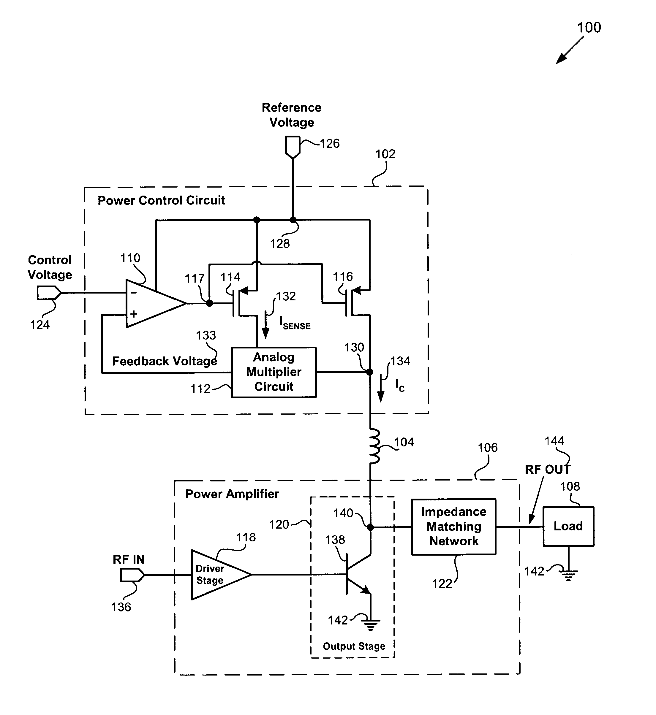
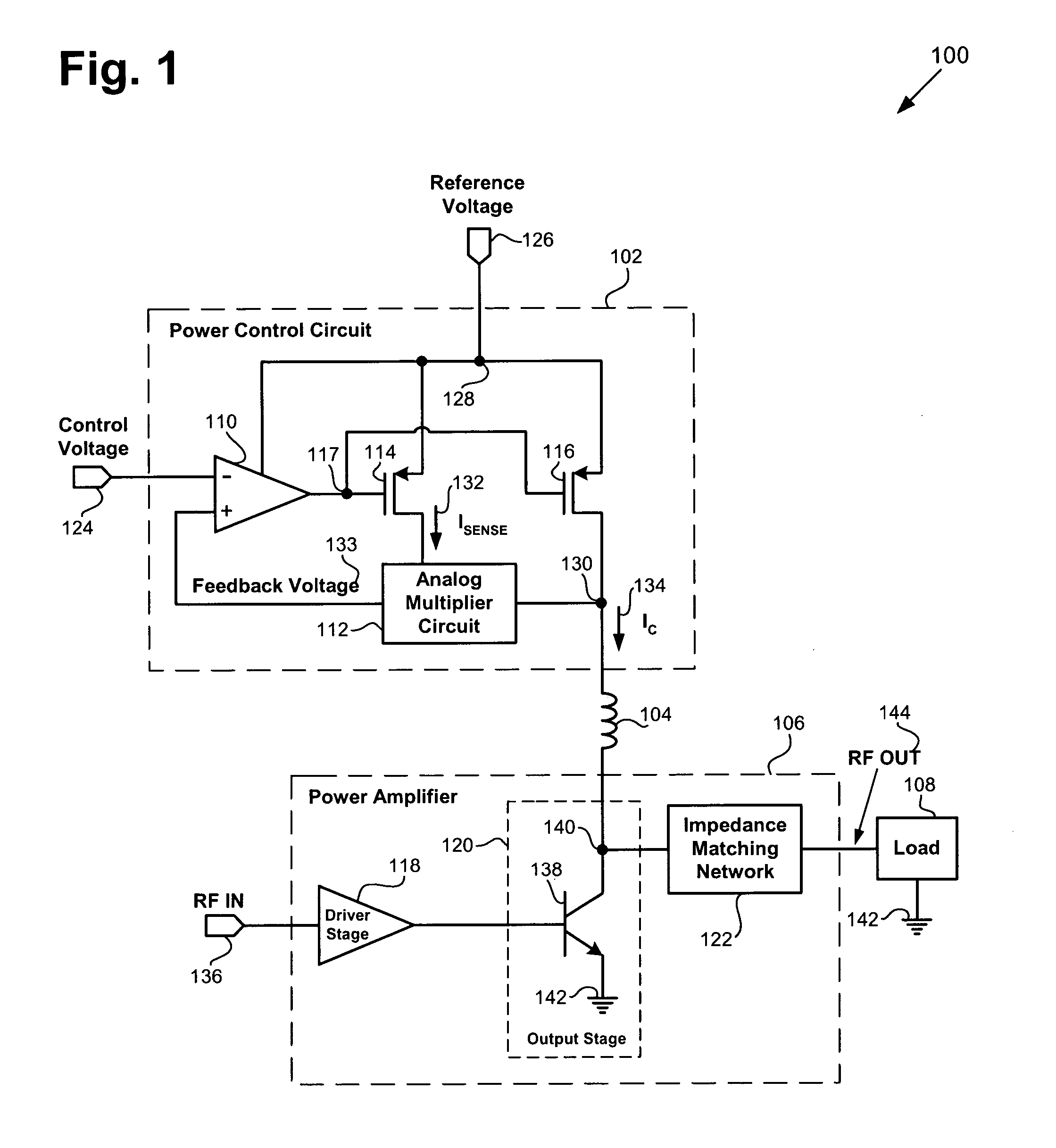
[0017]FIG. 1 shows a circuit diagram of an exemplary amplification module including an exemplary power control circuit and an exemplary power amplif...


PUM


Abstract

According to an exemplary embodiment, an amplification module includes a power control circuit. The amplification module further includes a power amplifier coupled to the power control circuit and configured to draw a supply current and receive a supply voltage from the power control circuit. The power control circuit is configured to control a DC power provided to the power amplifier by controlling a product of a sense current, which is a mirror current of the supply current, and the supply voltage. The power control circuit includes a feedback voltage that corresponds to the product of the sense current and the supply voltage. The power control circuit further includes an analog multiplier circuit configured to receive the sense current and the supply voltage and generate the feedback voltage. The power control circuit further includes a differential error amplifier configured to compare the feedback voltage to a control voltage.

Description

BACKGROUND OF THE INVENTION[0001]1. Field of the Invention[0002]The present invention is generally in the field of electrical circuits. More specifically, the invention is in the field of power amplifiers.[0003]2. Related Art[0004]Power amplifiers used in the transmitter section of communications devices, such a wireless handsets, are required to operate under a wide variety of operating conditions, such as variations in temperature and supply voltage, and variations in load impedance. Under these varying operating conditions and load impedance, it is highly desirable for power amplifiers to maintain a constant output power. As a result, various techniques have been employed in an attempt to control the output power of a power amplifier.[0005]However, current techniques for controlling the output power of a power amplifier suffer various disadvantages. For example, techniques that indirectly control the output power by controlling the voltage or current, such as collector voltage or...

Claims


Application Information

Patent Timeline
Patent Type & Authority Patents(United States)
IPC IPC(8): H03G3/10H03B1/04
CPCH03F1/0216H03G3/004H03F2200/426H03F2200/471H03F2200/474H03F2200/462H03F3/20
Inventor RIPLEY, DAVID S.
Owner SKYWORKS SOLUTIONS INC
Why Eureka
Try Eureka