Metal foil for capacitor, solid electrolytic capacitor using the foil and production methods of the foil and the capacitor

a technology of solid electrolytic capacitors and metal foils, which is applied in the direction of liquid electrolytic capacitors, electrolytic capacitors, terminal applications, etc., can solve the problems of deterioration of capacitor properties, increased leakage current, and difficulty in controlling current distribution, so as to achieve stable capacitance and reduce leakage current

Active Publication Date: 2007-10-30
MURATA MFG CO LTD
View PDF12 Cites 19 Cited by
  • Summary
  • Abstract
  • Description
  • Claims
  • Application Information

AI Technical Summary

Benefits of technology

[0016]Also, the present inventors have found that etching layers can be formed only on the portions to be cathode parts by performing etching after protecting the portions to be anode-leading-out-parts of capacitor elements with a protective material, so that, in a subsequent step of attaching electrically conductive polymer to the cathode parts, the anode-leading-out-parts can be satisfactorily prevented from the treating solution creeping up by masking, and as a result, production of a capacitor having properties of stable capacitance and reduced leakage current can be achieved.

Problems solved by technology

These cracks, burrs and the like on the cut edge surface generated at the time of cutting give rise to deterioration of capacitor properties.
However, electrically conducting polymer easily spreads beyond the masking material toward the anode part, which results in increase of leakage current.
However, in this method, etching is likely to be localized on the cut end part of the foil and this makes it difficult to control the current distribution, and another problem is involved that the cut edge part is dissolved or the strength of the part is decreased so quickly that effective area of the element decreases, failing in achieving a mass-production process of etched foils having a stable quality.

Method used


Image

  • Metal foil for capacitor, solid electrolytic capacitor using the foil and production methods of the foil and the capacitor
  • Metal foil for capacitor, solid electrolytic capacitor using the foil and production methods of the foil and the capacitor
  • Metal foil for capacitor, solid electrolytic capacitor using the foil and production methods of the foil and the capacitor

Examples


example 1

Step of Making Cut Lines

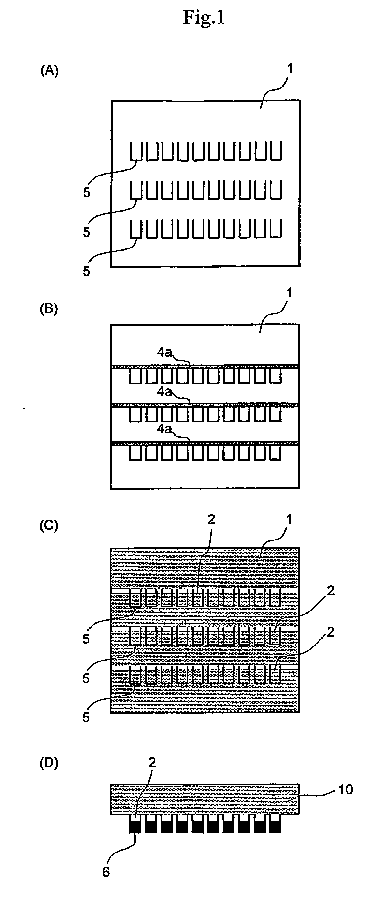
[0111]On a 200 μm-thick aluminum foil (containing Si: 20 ppm by mass, Fe: 24 ppm by mass, Cu: 33 ppm by mass and Ti: 0.9 ppm by mass), cut lines of a rectangular shape with one side open, each having a width of 200 μm were formed. Each of the rectangular shaped in cut lines to form a capacitor element had a width of 3 mm and a length of 6 mm. As shown in FIG. 1(A), cut lines for 30 capacitor elements were arranged in 3 lines×10 rows.

Etching Step

[0112]Both front and back surfaces of the portion working out to an anode-leading-out-part was covered with a 1 mm-wide resin tape as protective material (FIG. 1(B)) and then, the aluminum foil was dipped in a first electrolytic solution (10 mass % of hydrochloric acid+0.5 mass % of aqueous sulfuric acid solution) at 60° C. and etched by AC electrolytic etching under the conditions shown in Table 1.

Electrochemical Formation Step

[0113]The resin tape was removed (FIG. 1(C)) and a strip cut out in a comb-like shape from t...

example 2

[0120]Multilayer solid electrolytic capacitors were fabricated in the same manner as in Example 1 except for changing the thickness of aluminum foil from 200 μm to 300 μm. The measurement of leakage current and the reflow test were performed in the same manner. The results obtained are shown in Table 2.

example 3

[0121]Capacitors were completed in the same manner as in Example 1 except that in the etching step, the portion working out to the anode-leading-out-part was not protected by the protective material resin tape in Example 1. These capacitor elements were evaluated on the properties in the same manner as in Example 1. The results obtained are shown in Table 2.


PUM

PropertyMeasurementUnit
acute interior angleaaaaaaaaaa
thicknessaaaaaaaaaa
curvature radiusaaaaaaaaaa

Abstract

A metal foil for capacitor element is produced through a process including steps of etching and ten electrochemically forming a metal foil after making cut lines each in a shape of a capacitor element with at least a part of a portion predetermined to be an anode-leading-out-part left uncut. The step of etching the foil is preferably performed with the anode-leading-out-parts being protected by protective material. Solid electrolytic capacitor elements prepared by using the metal foil have narrow variation in capacitance.

Description

CROSS-REFERENCE TO RELATED APPLICATION[0001]This is an application based on the prescription of 35 U.S.C. Section 111(a) with claiming the benefit of filing date of U.S. Provisional application Ser. No. 60 / 407,974 filed Sep. 5, 2002 under the provision of 35 U.S.C. Section 111(b), pursuant to 35 U.S.C. Section 119(e) (1).TECHNICAL FIELD[0002]The present invention relates to a method for producing a metal foil for capacitors used in various electronic instruments, and a capacitor prepared by using the foil. More specifically, the present invention relates to a method for etching and electrochemically forming a metal foil for multilayer solid electrolytic capacitors, and a solid electrolytic capacitor using a metal foil obtained by the method.BACKGROUND ART[0003]Developments of chip-type or small-size electronic components are aggressively proceeding to cope with the requirement for downsizing of electronic instruments, high-density packaging of print substrates, promotion of packagin...

Claims


Application Information

Patent Timeline
Patent Type & Authority Patents(United States)
IPC IPC(8): H01G9/00H01G9/04H01G9/045H01G9/15
CPCH01G9/012H01G9/042H01G9/045H01G9/055H01G13/006H01G9/028H01G9/15Y10T29/417Y10T29/41
Inventor KOBAYASHI, KENKISAWAGUCHI, TORUKONUMA, HIROSHI
Owner MURATA MFG CO LTD
Why Eureka
Try Eureka