Fluid-cooled cylinder liner

a technology of cylinder liners and fluids, which is applied in the direction of cylinders, machines/engines, mechanical equipment, etc., can solve the problems of increasing emissions, increasing the complexity of the cooling system, increasing the cost of manufacturing these engines, and increasing the weight of the cooling system. , to achieve the effect of reducing manufacturing costs and high thermal conductivity

Inactive Publication Date: 2007-11-06
BENMAXX
View PDF13 Cites 19 Cited by
  • Summary
  • Abstract
  • Description
  • Claims
  • Application Information

AI Technical Summary

Benefits of technology

[0016]In particularly preferred embodiments, the cylinder liner comprises ‘carbon graphite foam’. Preferably, infusion casting is used. For example, an aluminum-based alloys (e.g., eutecic, hypereutectic, or otherwise), with or without particulate reinforcement are cast into (e.g., infiltration casting) a ‘preform’ of porous ‘carbon graphite foam’ (with or without particulate reinforcement, such as silicon carbide). Carbon graphite foam (developed at Oak Ridge National Laboratory, USA) has high thermal conductivity and also acts as super-conductor (see, e.g., U.S. Pat. Nos. 6,673,328, 6,663,842, 6,656,443, 6,398,994, 6,387,343 and 6,261,485, all of which are incorporated by reference herein in their entirety). Preferably the silicon carbide volume should be from about 10% to 35% to provide desired friction at wear plate rubbing surface. Infiltration of un-reinforced or reinforced alloy into carbon graphite foam ‘preform’ is during a suitable casting procedure including, but not limited to die casting, high-vacuum permanent mold casting, squeeze casting, or centrifugal casting. According to the present invention, carbon graphite foam can be included in the compositions of at least one of the cylinder liner, and any parts in contact therewith. According to the present invention, the use of carbon graphite foam ‘preforms’ not only substantially reduces manufacturing costs (e.g., relative to the use of ceramic ‘preforms’), but provides an environmentally responsible cylinder liner, because carbon graphite foam is manufactured from a by-product of coal fabrication.

Problems solved by technology

The heat generated by internal combustion engines tends to degrade many of the components of the engine.
The high heat at which these engines run also tends to increase emissions, especially of nitrogen oxide.
The complexity of these cooling systems has increased not only the expense of manufacturing these engines, but also their weight and the potential for flaws in the cooling system—both during manufacture and while in use.
The use of cylinder liners helps alleviate degradation of the cylinder bore due to the heat, but in turn creates problems related to degradation of the cylinder liners due to excessive heating.
Thus, cylinder liners are a fourth component of internal combustion engines that are subject to degradation and failure due to excessive heating.
The complexity of the layout of the passages and process of circulating the cooling medium uniformly round all of the cylinder bores is especially accentuated in engines where the cylinder bores are arranged in a “V”-formation (e.g., V-8s and V-12s) because these engines tend to have reservoirs for the cooling medium arranged on one-side of the engine; necessitating a complex series of passages to circulate fluids to the other side.
In addition to the increased cost of engine block design and manufacture necessitated by the current dry-sleeve or wet-sleeve design, a primary shortcoming of the wet-sleeve design is the non-uniform distribution of the cooling fluid surrounding the cylinder liner.
The non-uniform distribution leads to uneven cooling of the liner, the development of hot spots, and the eventual cracking or failure of the liner.
However, while this design increases the surface area of the liner that is exposed to the cooling medium, it fails to address the problem of non-uniform distribution of the cooling fluid because the fluid is not in contact with the entire axial length of the liner.
This design also does not reduce the requirement for a complex series of passages within the engine block for circulating the cooling medium to and from the area between the cylinder bore and the cylinder liner.
Furthermore, the design increases the complexity and manufacturing cost of producing cylinder liners by changing the typically planar outer surface of the liner to “an outer surface with a plurality of peaks and valleys” (see U.S. Pat. No. 6,675,750 patent, at col.
Additionally, while the above-described designs and approaches are directed at cooling the cylinder areas, they do not address the problem presented by engine ‘cold-start’ and idle periods; during which times substantial excessive pollution / emissions are generated because the cylinders are not at an appropriate temperature to provide for optimally efficient combustion.
This is a serious problem in the trucking industry, and has led to increasingly more stringent regulations regarding idling periods.
Therefore, the above-described prior art efforts to improve cooling of cylinder liners actually create additional problems from the standpoint of pollutants being generated during cold-starting and idling.

Method used


Image

  • Fluid-cooled cylinder liner
  • Fluid-cooled cylinder liner
  • Fluid-cooled cylinder liner

Examples


Embodiment Construction

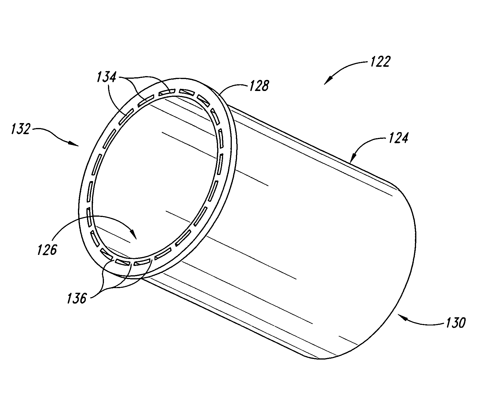
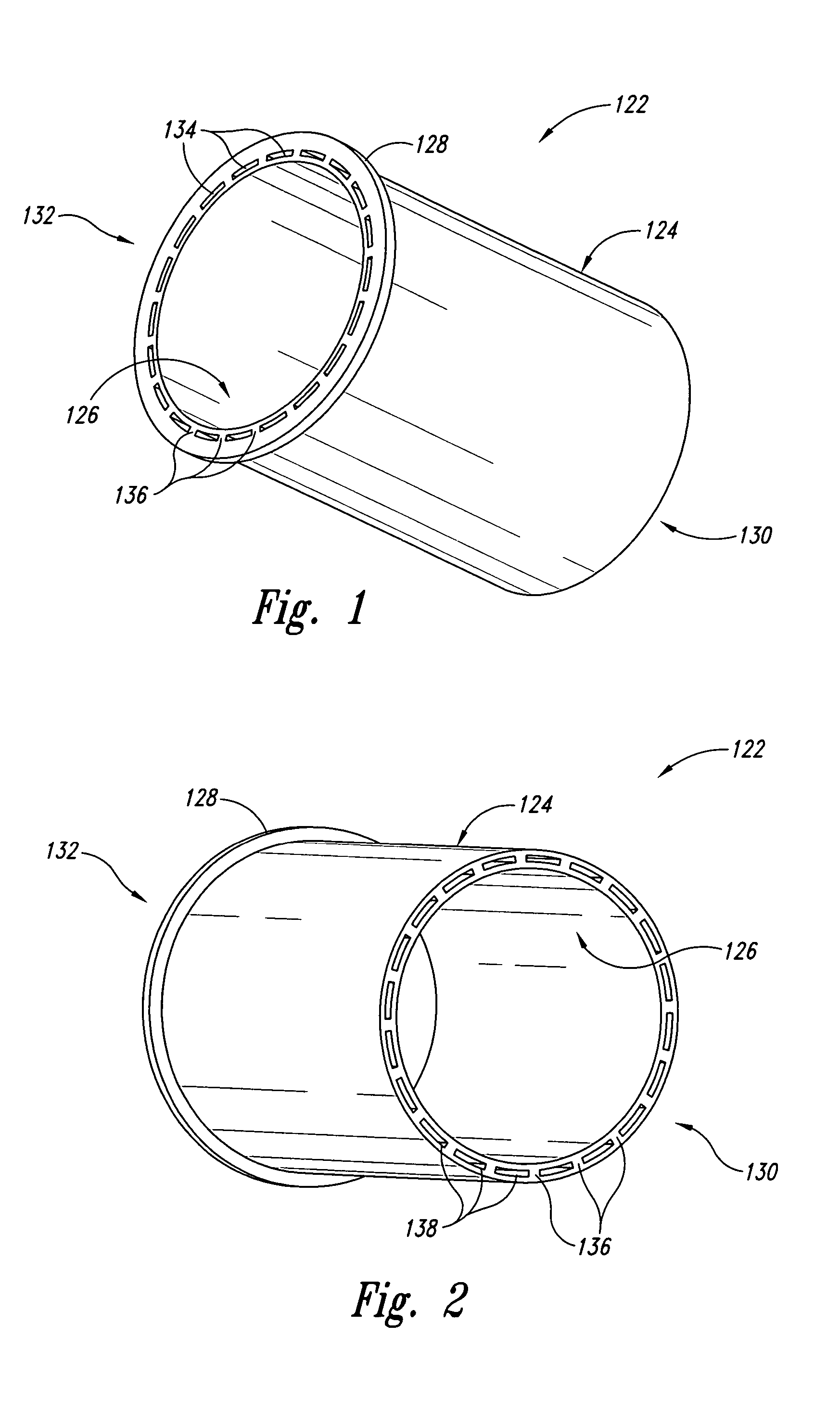
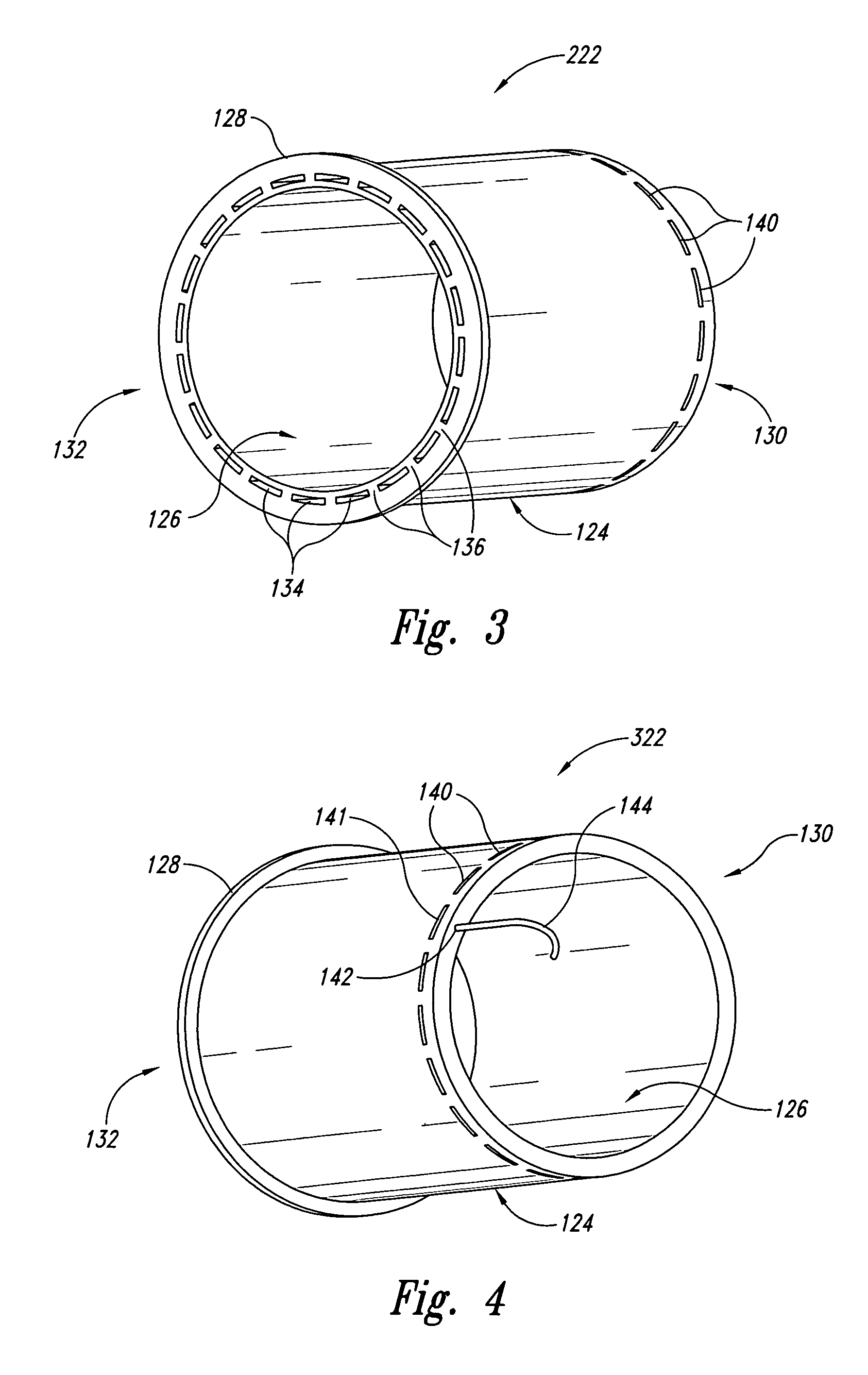
[0023]Particular embodiments of the present invention provide novel fluid-cooled cylinder liners. Preferred liners are generally in the shape of annular cylinders and contain a plurality of passages; arranged parallel to the axis of the cylinder, between the inner and outer surfaces of the cylinders. Preferred passages are arranged so that they are typically closer to the outer surface of the cylinder than the inner surface. Each passage has at least two openings. Openings that appear at either end of the cylinder are referred to herein as “ports,” whereas those that appear along the inner or outer surface of the cylinder are referred to herein as “windows.” Thus, a passage with two ports (with one on either end of the cylinder) would run the entire length of the cylinder, while a passage with a port and a window or a passage with two windows would run only for a fraction of the cylinder length. Although windows can be arranged at any position along the outer or inner surfaces of th...


PUM


Abstract

Particular embodiments of the present invention provide novel fluid-cooled cylinder liners. Preferred liners are annular cylinders containing a plurality of passages, arranged generally parallel to the axis of the cylinders, and integrated between the inner and outer surfaces of the cylinders. Preferably, the integral passages are arranged so that they are typically closer to the outer surface of the liner than the inner surface. Each passage has at least two openings. A passage with two openings on opposite end of the cylinder runs the entire length of the liner, while a passage with a opening at one end of the liner and a second opening along a surface of the liner runs only for a fraction of the liner length. In preferred embodiments, openings on the outer surface of the liner will be arranged in a circle lying on a plane perpendicular to the axis of the cylinder, and near either end of the cylinder; ensuring that each passage traverses the majority of the length of the liner. Preferably, the cylinder liners comprise at least one material selected from the group consisting of aluminum, a aluminum-based metal matrix composite (MMC) with a particulate reinforcement, superalloys, ceramic matrix composite (CMC), and carbon graphite foam. Preferably, the liners comprise a heating element.

Description

CROSS-REFERENCE TO RELATED APPLICATIONS[0001]This application claims the benefit of priority to U.S. Provisional Patent Application Ser. No. 60 / 542,955 filed 9 Feb. 2004 and entitled FLUID-COOLED CYLINDER LINER, and to U.S. Provisional Patent Application Ser. No. 60 / 646,239, filed 21 Jan. 2005 of same title, both of which are incorporated by reference herein in their entirety.FIELD OF THE INVENTION[0002]The invention generally relates to cooling or preheating internal combustion engines, and more particularly to cooling or preheating cylinder liners by passing fluids through internal passages in the cylinder liners.BACKGROUND[0003]A direct result of the increased horsepower of modern automotives engines is the proportional increase in the heat generated by these engines. The heat generated by internal combustion engines tends to degrade many of the components of the engine. The high heat at which these engines run also tends to increase emissions, especially of nitrogen oxide. The E...

Claims


Application Information

Patent Timeline
Patent Type & Authority Patents(United States)
IPC IPC(8): F02F1/10F02F1/16
CPCF02F1/16
Inventor RAU, III, CHARLES BENJAMINJOLLEY, JR., DALLAS W.
Owner BENMAXX
Why Eureka
Try Eureka