
System, method, and apparatus for passive, multi-spectral, optical identification of remote objects

a remote object and optical identification technology, applied in the field of object identification systems, can solve problems such as equipment damage, and achieve the effect of easy and rapid identification

Active Publication Date: 2007-11-06
LOCKHEED MARTIN CORP
View PDF9 Cites 5 Cited by
  • Summary
  • Abstract
  • Description
  • Claims
  • Application Information

AI Technical Summary

Benefits of technology

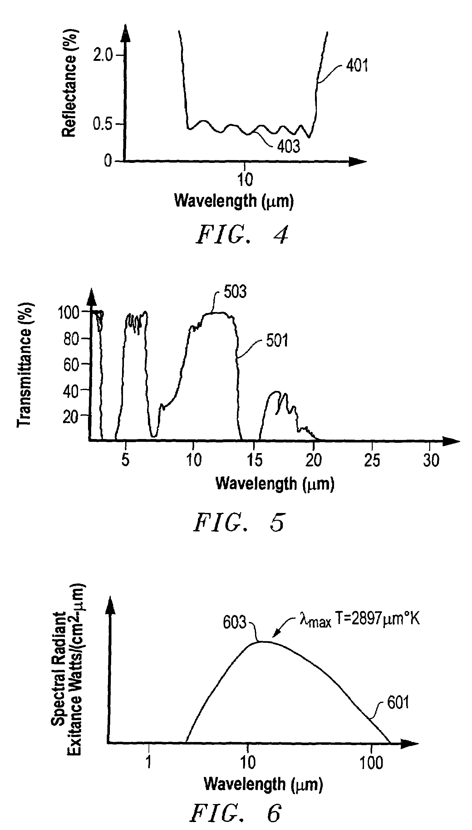
The present invention is a system, method, and apparatus that uses an integrated, two-dimensional pattern, spectral tailoring, and an imaging system to passively identify objects at large distances. The system uses a tailored reflective surface that only reflects energy in a very narrow wavelength band, making the objects easily and rapidly identifiable by optical means. The system can detect the signatures on the objects using a scanner that can detect the narrow wavelength band of each signature. The signatures are designed to be distinguishable from other signatures at a required distance for the resolution capability of a particular detector or scanner. The system can passively record the light emanating from the signature in the specific band and recognizes the signature to discern what the object is based on a database of information. The technical effects of the invention include the ability to easily and rapidly identify objects of various origin and configuration, including equipment, aircraft, tanks, etc.

Problems solved by technology

Unfortunately, these signals can be detected by other surveillance systems, including hostile systems, which can use the signals to track and destroy the equipment.

Method used


Image

  • System, method, and apparatus for passive, multi-spectral, optical identification of remote objects
  • System, method, and apparatus for passive, multi-spectral, optical identification of remote objects
  • System, method, and apparatus for passive, multi-spectral, optical identification of remote objects

Examples


Embodiment Construction

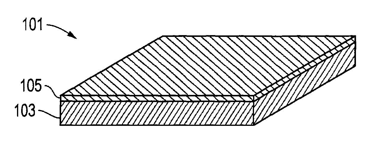
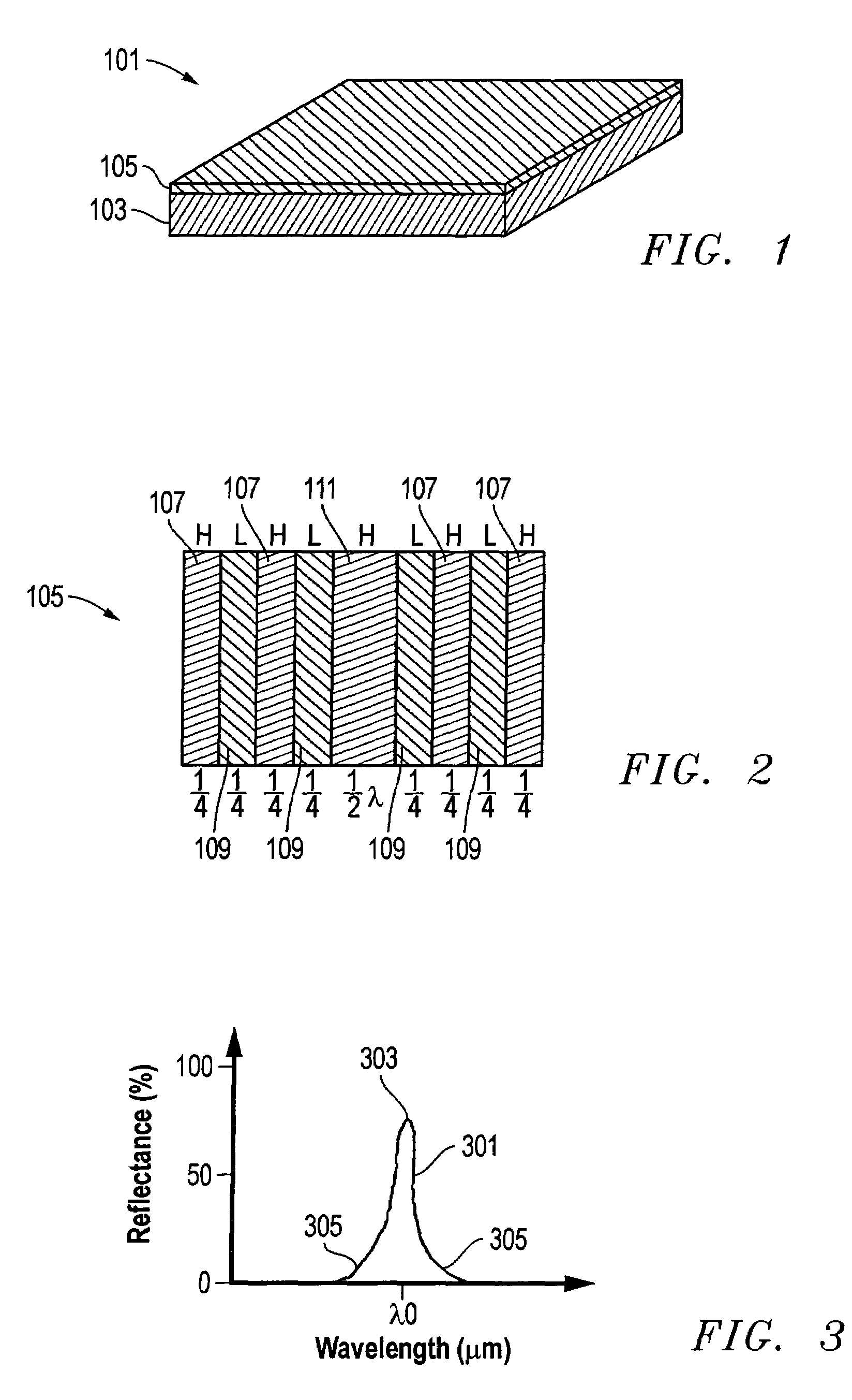
[0019]Referring to FIG. 1, one embodiment of a signature 101 constructed in accordance with the present invention is shown. The signature 101 is part of a system that is designed to reflect light, such as infrared light, at very limited wavelengths in order to remotely identify an object.

[0020]Signature 101 comprises a laminate of materials having a substrate 103, such as Mylar, and a thin film 105 mounted on a surface of the substrate 103. As shown in FIGS. 1 and 2, the thin film 105 may comprise a dielectric, vapor-deposited, multi-layer laminate. In the embodiment of FIG. 2, the thin film 105 comprises a plurality of layers 107 having a high index of refraction that are interleaved with a plurality of layers 109 having a low index of refraction. Each of the layers 107, 109 has a thickness of one-quarter wavelength, other than a center, high index layer 111, which has a thickness of one-half wavelength.

[0021]The properties and characteristics of the wavelength bands utilized by th...


PUM


Abstract

A system passively identifies objects at large distances with an integrated two-dimensional pattern, spectral tailoring, and an imaging system. Encoded information allows objects of various origin and configuration to be easily and rapidly identified by optical means, but is invisible to the naked eye. The devices used for detecting the objects may be ground-based, airborne, or even satellite-based, and can track engagements of such marked objects in real-time. A tailored reflective surface at a specific wavelength band is applied to the exteriors of the objects to form a unique signature. A scanning system passively records the light emanating from the signature in the specific band, and recognizes the signature to discern what the object is based on a database of information.

Description

BACKGROUND OF THE INVENTION[0001]1. Technical Field[0002]The present invention relates in general to an improved object identification system and, in particular, to an improved system, method, and apparatus for passively identifying objects at long range with a multi-spectral, optical signature and detector.[0003]2. Description of the Related Art[0004]Current flight-based, object identification systems are active in that they require the objects-to-be-identified to emit an active, trackable signal in order to be identified. Typically, radio signals are emitted by the objects in order to identify them. The radio signals contain information about who and / or what the objects or equipment are. Unfortunately, these signals can be detected by other surveillance systems, including hostile systems, which can use the signals to track and destroy the equipment. Although active identification systems are workable, a passive system for identifying objects that does not require the objects to re...

Claims


Application Information

Patent Timeline
Patent Type & Authority Patents(United States)
IPC IPC(8): G06F7/10G06K19/06
CPCG06K19/06009
Inventor BETUSH, WILLIAM J.REED, JAMES R.TORTI, RUSSELL G.
Owner LOCKHEED MARTIN CORP
Learn More