Light guide plate and manufacturing method of the same

a technology of light guide plate and manufacturing method, which is applied in the direction of lighting and heating apparatus, instruments, other domestic objects, etc., can solve the problems of requiring too much material to fabricate, consuming too much power hazardous radiation, etc., and achieves the goal of reducing production costs, improving the degree of sophistication of light guide plate, and simplifying the fabrication process

Active Publication Date: 2007-11-06
AU OPTRONICS CORP
View PDF14 Cites 0 Cited by
  • Summary
  • Abstract
  • Description
  • Claims
  • Application Information

AI Technical Summary

Benefits of technology

[0011]Accordingly, the present invention is directed to a method of manufacturing a light guide plate that can simplify the fabrication process, lower the production cost and increase the degree of sophistication of the light guide plate.
[0012]The present invention is directed to a light guide plate having a smaller overall thickness and a lower possibility of light leakage from the light guide plate.
[0019]In brief, the method of fabricating the light guide plate includes providing a thin film having a transfer material layer thereon and then simultaneously transferring the transfer material layer to the light guide plate when the light guide plate body is formed in a molding process. Hence, not only is the fabricating process of the light guide plate greatly simplified, but also reduces the overall thickness of the light guide plate because a conventional reflector is no longer required. Moreover, the method permits the production of a highly sophisticated light guide plate and the tape transfer mechanism speeds up the delivery of thin film to the molding machine.

Problems solved by technology

However, from an environmental point of view, CRT tends to consume too much power, requires too much material to fabricate and always produces hazardous radiation in the process of operation.
However, this method of fabricating the light guide plate is rather complicated and frequently affects other processing parameters (for example, the flow drag of molding compound affected by the protrusion pattern, the homogeneity of etching, the cooling rate and so on).
Consequently, the reproducibility of the fabricated light guide plate 110 is rather low and product yield is hardly improved.
Nevertheless, attaching the reflector 130 to the light guide plate 110 increases not only processing time and production cost, but also the overall thickness of the back light module 100.

Method used


Image

  • Light guide plate and manufacturing method of the same
  • Light guide plate and manufacturing method of the same
  • Light guide plate and manufacturing method of the same

Examples


Embodiment Construction

[0028]Reference will now be made in detail to the present preferred embodiments of the invention, examples of which are illustrated in the accompanying drawings. Wherever possible, the same reference numbers are used in the drawings and the description to refer to the same or like parts.

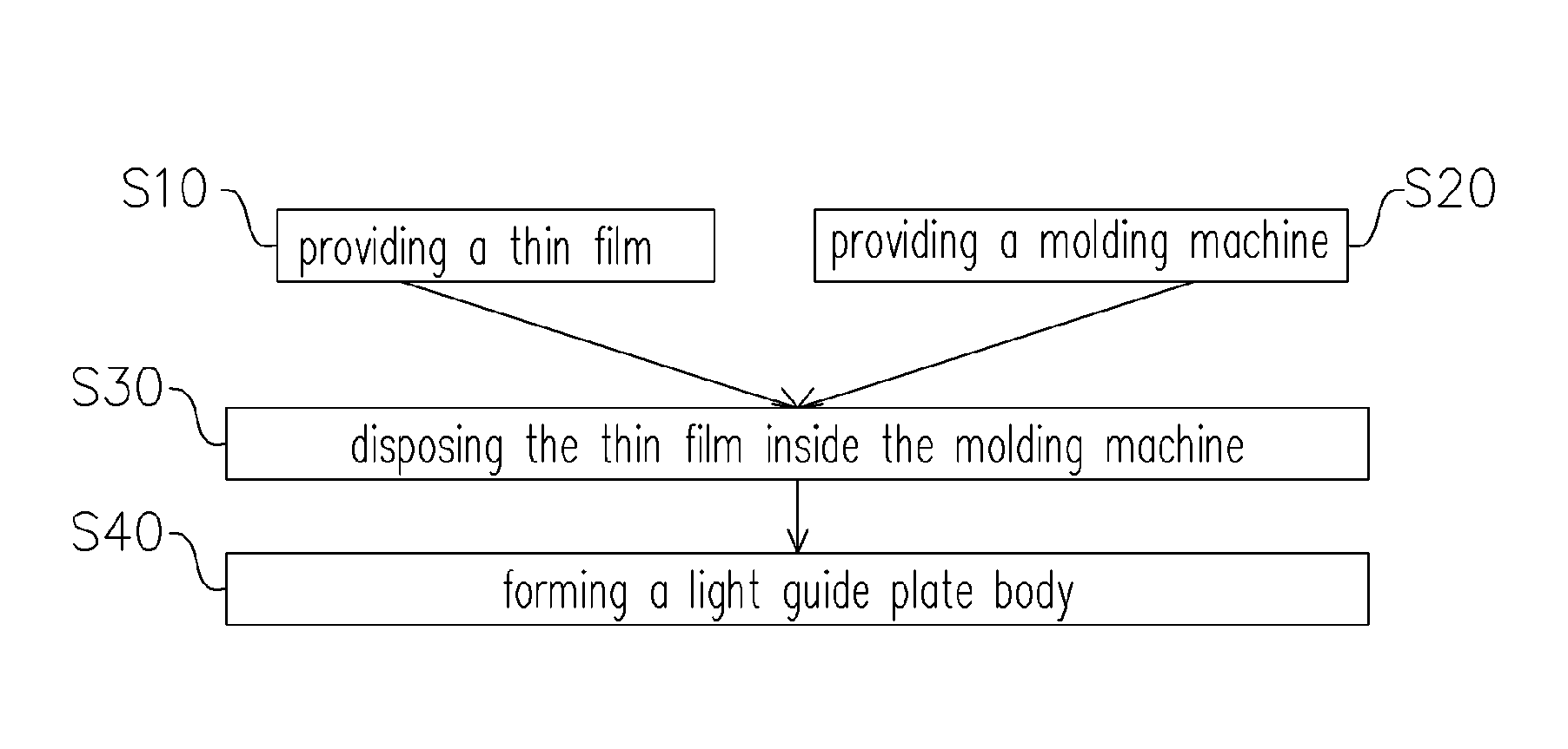
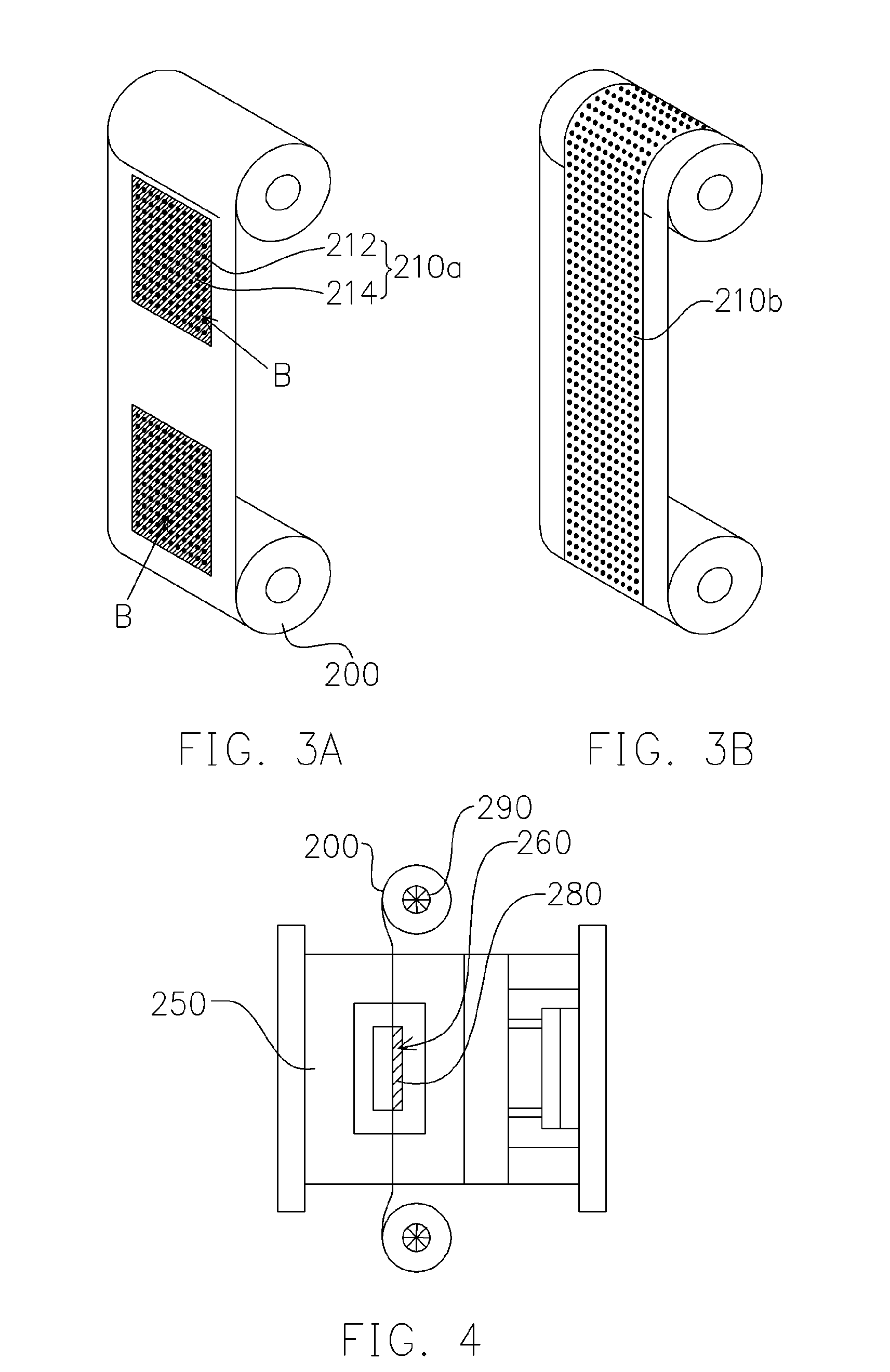
[0029]FIG. 2 is a flow diagram showing the steps for producing a light guide plate according to one embodiment of the present invention. FIGS. 3A and 3B show two types of tape transfer systems for delivering thin films according to an embodiment of the present invention. To form a light guide plate, a thin film 200 having a transfer material layer 210a thereon is provided (step S10) as shown in FIGS. 2 and 3A. The thin film 200 is a spool of tape fabricated using polyester (PET), for example.

[0030]The transfer material layer 210a are disposed on the thin film 200 as patterned blocks B (shown in FIG. 3A) or the transfer material layer 210b are disposed on the thin film 200 as a continuous band (shown ...


PUM

PropertyMeasurementUnit
distanceaaaaaaaaaa
brightnessaaaaaaaaaa
thicknessaaaaaaaaaa

Abstract

A method of manufacturing a light guide plate comprising the following the steps. First, a thin film with a transfer material layer thereon is provided. Thereafter, a molding machine having a molding cavity therein is provided. A thin film is disposed in the molding machine such that at least part of the transfer material layer is located inside the molding cavity. A light guide plate body is formed inside the molding cavity so that the transfer material layer is transferred onto the light guide plate body at the same time.

Description

CROSS REFERENCE TO RELATED APPLICATIONS[0001]This application claims the priority benefit of Taiwan application serial no. 93111205, filed Apr. 22, 2004.BACKGROUND OF INVENTION[0002]1. Field of the Invention[0003]The present invention relates to a light guide plate and manufacturing method thereof. More particularly, the present invention relates to a light guide plate fabricated by a transfer process.[0004]2. Description of Related Art[0005]Due to the rapid development of semiconductor devices and man-machine interfaces, multi-media systems have found wide applications. In the past, cathode ray tube (CRT) is a dominant type of displays on the market because of its superb display quality and low production cost. However, from an environmental point of view, CRT tends to consume too much power, requires too much material to fabricate and always produces hazardous radiation in the process of operation. Hence, with considering the production of light, compact, low power rating, radiati...

Claims


Application Information

Patent Timeline
Patent Type & Authority Patents(United States)
IPC IPC(8): F21V7/04B29D11/00G02B6/00F21V7/00F21V8/00F21Y103/00G02F1/13357
CPCG02B6/0043G02B6/0065G02B6/0055
Inventor CHENG, SHIH-MING
Owner AU OPTRONICS CORP
Why Eureka
Try Eureka