Overland cargo restraint system and method

a cargo restraint and cargo technology, applied in the direction of load securing, transportation and packaging, transportation items, etc., can solve the problems of emergency braking, trucks are subject to stopping and starting forces, and the mass of transport loads can produce considerable momentum force, etc., to achieve efficient and simple removal of the securing system and effective use

Active Publication Date: 2007-11-06
MBULL HLDG LLC
View PDF1 Cites 38 Cited by
  • Summary
  • Abstract
  • Description
  • Claims
  • Application Information

AI Technical Summary

Benefits of technology

[0020]It is a general object that the subject invention provide a novel system and method to secure a load within a transport container which will obviate or minimize problems and concomitantly achieving many of the desired aspects of lading securement of the type previously described.
[0021]It is another general object of the subject invention to judiciously protect cargo from damage during transport and to provide enhanced securement of a load within a container while minimizing shifting of a container load for overland transport.
[0022]It is a specific object of the invention to provide a securement system and method for an a truck body, truck trailer, railroad boxcar, and the like, with enhanced ease of application to restrain a load in position during impact and / or other transport forces and reduce travel of lading within an overland transport container.

Problems solved by technology

Although each containment enclosure or bundle may be quite heavy and stationary at rest, the mass of a transport load can produce considerable momentum force as overland cargo is placed in motion.
In this regard trucks are subject to stopping and starting forces, emergency braking, bumps and swaying from uneven road beds, centrifugal forces on curves, vibration, etc., which tend to shift loads.
When a railroad car is rolled into a stationary string of cars, the impact causes the car couplings to lock together with a jolt.
Moreover, during transport, railway cars are subject to braking forces, run-in and run-out coupler impacts over grades, rail vibration, dips in the track, and swaying.
Such forces can result in damage to the cargo, damage to the interior walls or doors of the container, damage to the cargo packing, and may create dangerous leaks if the cargo is a hazardous material.
Accordingly, it is undesirable to permit cargo to gain any momentum independent of a container during transport.
Each of these previously known systems for securement has limitations associated with construction cost, lack of strength sufficient to secure heavy loads, etc.
Moreover, although rear doors of a trailer may be relied on to at least partially secure non-hazardous materials such as food-stuffs, tissue or soft paper products, furniture, appliances, etc., for hazardous materials, and many other types of loads, the rear doors of a container may not be used to even partially secure a load.
In this instance it may be impractical to construct wooden front and rear dunnage sufficient to secure a load where the front of the trailer is not utilized.
This, however, can be a costly, time consuming, and generally inefficient means of securing a load.
In this, the blocking process requires carpenters and is often outsourced to contractors.
Moreover, wooden barriers can be time consuming to install.
Further wood bracing can be somewhat brittle and subject to failure as a result of an abrupt impact.
When wood bracing is utilized as a system of restraint, because of the bracing system bulk, shippers may be forced to ship containers that are not filled to capacity.
This reduces transport efficiency and increases transportation costs.
Moreover, some types of wood, such as conifer woods, are not acceptable to cross international boundaries without certification of special fumigation or heat treatment processing of conifer wood dunnage.
Other known means of restraint such as ropes, metal or plastic straps or stands and the like appearing in the past have tended to exhibit impaired performance and are often not functionally suitable to restrain loads under even moderate conditions.
In addition to the above, other restraining systems known in the past required multiple elements and equipment which were cumbersome to store, were arduous to install, and often required a degree of skilled labor.
Systems using straps, nails, anchors, bolts, or other tools all require substantial storage space even when not in use.
Furthermore, such systems increase the safety risk to the workers restraining the cargo.
Still further such systems have often been unable to satisfy safety and travel limits imposed by regulatory bodies in various countries.
In addition to the above concerns, systems and procedures used in the past relying on accessories located within the cargo container were often not able to secure a partial load.
That is, if the load does not extend to the front or rear of the container, such as a centrally located load, the necessary anchors may not be available in an area where they can be effectively used.
In addition to this requirement of a separate adhesive, systems appearing in the past sometimes encountered problems associated with weakness at the joints.

Method used


Image

  • Overland cargo restraint system and method
  • Overland cargo restraint system and method
  • Overland cargo restraint system and method

Examples


Embodiment Construction

Context of the Invention

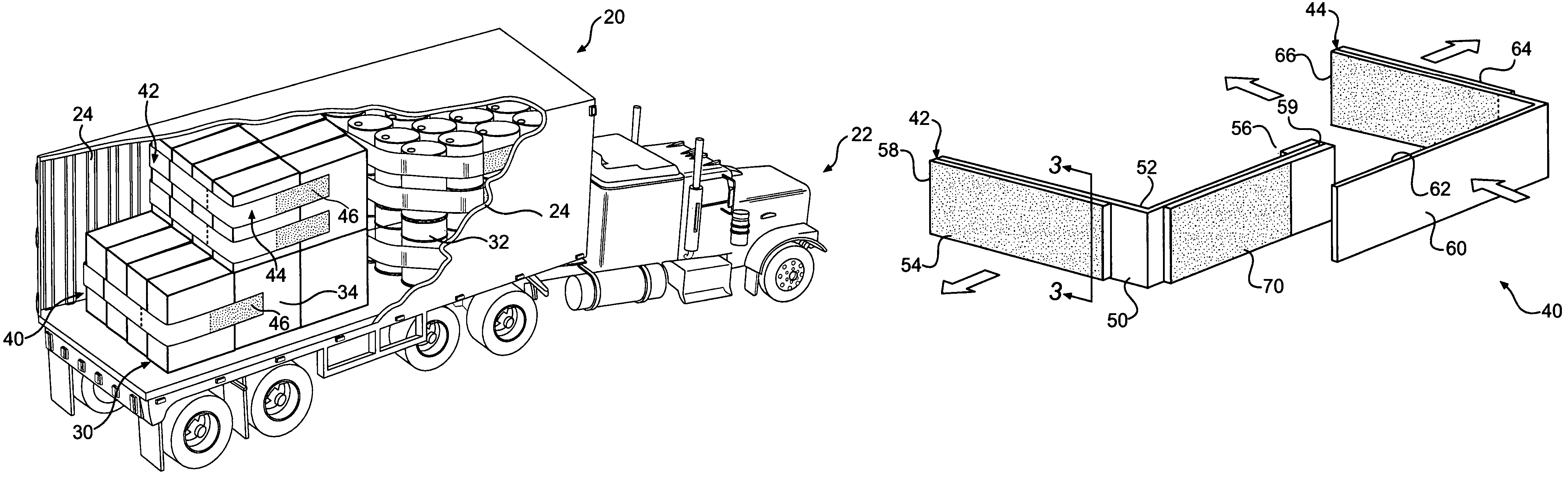
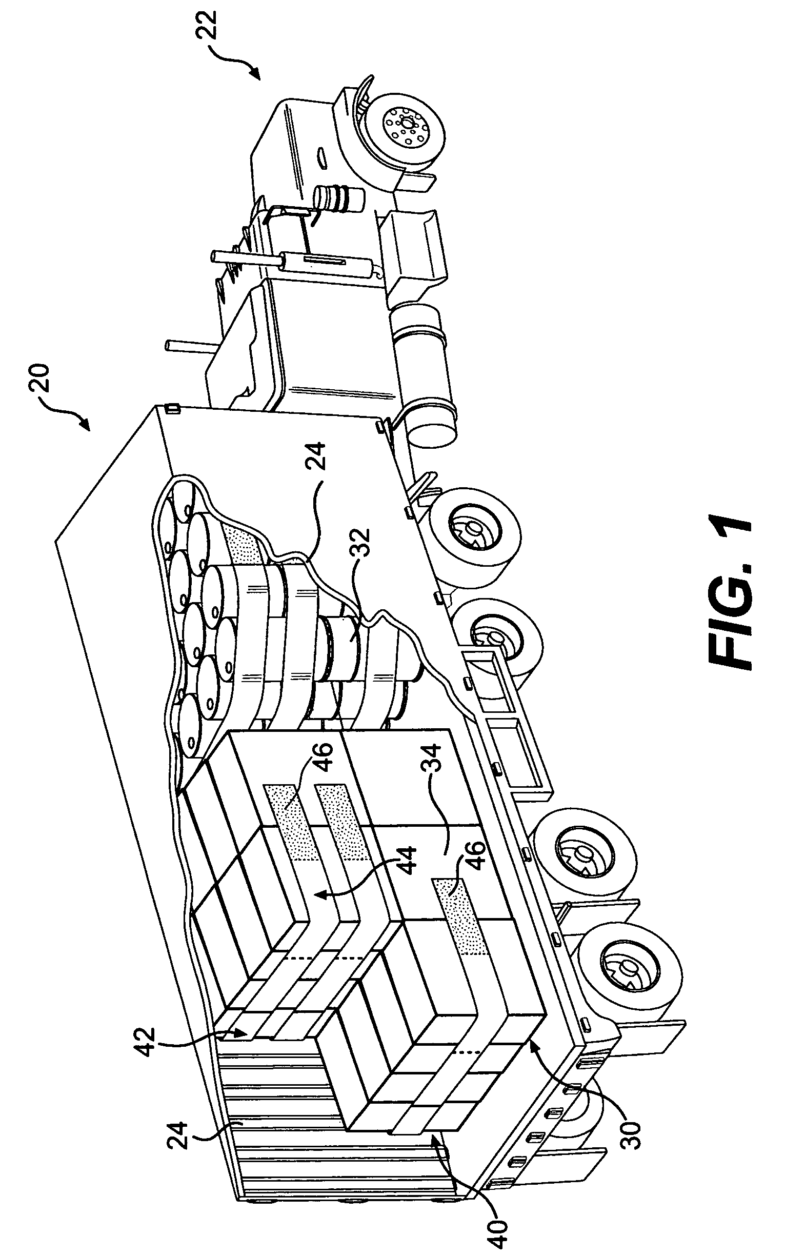
[0037]FIG. 1 shows an axonometric view of an operating environment of the invention. In this view, a transport or cargo container 20, such as a truck body or truck trailer, is shown towed by a tractor 22 for land transport. Trailers 20 such as these are also operable to be mounted on railway flat cars. Trailer 20 carries cargo 30 to be restrained, such as fifty five gallon drums 32, boxes 34, plastic wrapped pallets, and the like (not shown).

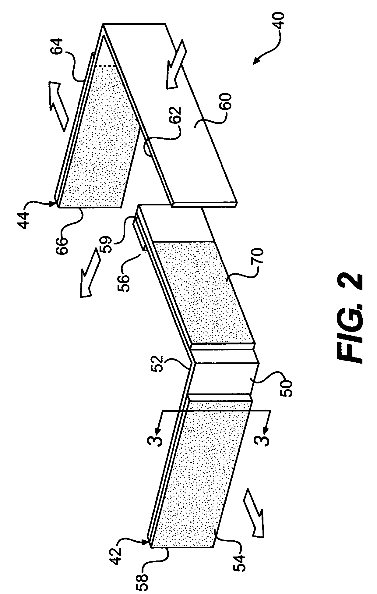
[0038]A partially cut away portion of FIG. 1 depicts a load restraining system 40 in accordance with the invention, which is operable to be adhered to an interior wall surface 24 of the trailer 20. The load restraining system 40 shown in FIG. 1 comprises a pair of opposing restraining strips. A first load restraining strip 42 and a second load restraining strip 44 are adhered to the interior side walls 24 of the trailer 20 by the use of adhesive elements 46 that are operable to self adhere to opposing interior side walls ...


PUM


Abstract

The present invention is directed to a load restraining system and method for securing cargo within a transport container, which is subject to shifting forces. A system includes first and second load restraining strips that cab be self-adhered onto interior wall surfaces of a transport container and extend across cargo within the container. The first load restraining strip has a first adhesive element, which can engage an interior wall surface, and a second adhesive element on a second side, which can engage a surface of cargo to be restrained. A second load restraining strip has a third adhesive element on a first side, which engage an interior wall surface of the container. A fourth adhesive element connected to one of the load restraining strips is operable to secure the two load restraining strips together. A method for securing cargo within a transport container includes providing first and second load restraining strips having adhesive elements, attaching each load restraining strip to internal wall surfaces of a transport container, wrapping the free ends of the load restraining strips around cargo to be restrained, and mutually securing the load restraining strips across cargo.

Description

RELATED PATENTS[0001]This application relates to U.S. Pat. No. 6,089,802 entitled “Cargo Restraint System for a Transport Container” issued on Jul. 18, 2000; U.S. Pat. No. 6,227,779 entitled “Cargo Restraint Method for a Transport Container” issued on May 8, 2001; and U.S. Pat. No. 6,607,337 entitled “Cargo Restraint System” issued on Aug. 19, 2003, all of common inventorship and assignment as the subject application. This application further relates to application for patent Ser. No. 10 / 730,024 entitled “Laminated Cargo Restraint System and Method” filed on Dec. 9, 2003; application for patent Ser. No. 10 / 730,025 entitled “Monolithic Cargo Restraint System and Method”, filed on Dec. 9, 2003; application for patent Ser. No. 10 / 730,042 entitled “Cross-weave Cargo Restraint System and Method”, filed on Dec. 9, 2003; and application for patent Ser. No. 10 / 730,040 entitled “Cargo Restraint System and Method”, filed on Dec. 9, 2003.BACKGROUND OF THE INVENTION[0002]This invention relates ...

Claims


Application Information

Patent Timeline
Patent Type & Authority Patents(United States)
IPC IPC(8): B60P7/08
CPCB60P7/0823B61D45/001B60P7/135
Inventor BULLOCK, MATTHEW
Owner MBULL HLDG LLC
Why Eureka
Try Eureka