Injection molding method and apparatus for continuous plastication

a technology of injection molding and injection shot, which is applied in the direction of auxillary shaping apparatus, manufacturing tools, food shaping, etc., can solve the problems of limiting the amount of time available for plasticizing the next injection shot, affecting the efficiency of the injection process, and the high speed translation of the screw relative to the hopper feed throat, so as to reduce the energy demand, increase the rotation time of the screw, and increase the output efficiency

Inactive Publication Date: 2007-11-06
HUSKY INJECTION MOLDING SYST LTD
View PDF18 Cites 56 Cited by
  • Summary
  • Abstract
  • Description
  • Claims
  • Application Information

AI Technical Summary

Benefits of technology

[0017]An advantage of the present invention is the increased output efficiency and decreased energy demand of RS injection units operated in accordance with the apparatus and methods described herein. The present invention features structure and / or steps whereby the screw rotation time is increased substantially, thereby improving the injection molding machine's output efficiency.
[0018]According to a first aspect of the present invention, structure and / or steps are provided for a reciprocating screw injection unit having a cyclic operating period. The unit includes an axially translating screw mounted within a barrel, the screw having associated therewith a non-return valve downstream of which a volume of melt can, in use, be accumulated. The unit also includes a first actuator arranged to effect axial movement of the screw relative to the barrel and to generate, in use, back-pressure. A second actuator is coupled to the screw to control, in use, the rotational speed of the screw. The unit further includes a controller for controlling operation of the screw and the first actuator, the controller arranged to set an axial position for the screw that defines the volume of melt to be accumulated downstream of the non-return valve by effecting, in use, an increase in the back-pressure to prohibit any further increase in the volume for melt accumulation and to render a recovery rate for the screw of substantially zero, and wherein the controller is arranged to ensure that the screw, during use, rotates substantially continuously over the entire cyclic operating period.
[0019]According to a second aspect of the present invention, structure and / or steps are provided for a reciprocating screw injection unit developing injection pressures for injection purposes. The reciprocating screw injection unit includes a screw within a barrel having a shot chamber into which molten material is accumulated, the injection unit having an adjustable recovery rate. The reciprocating screw injection unit includes means for dynamically varying revolutions per minute of the screw within the barrel, means for adjusting back-pressure developed by the injection unit to control location and axial movement of the screw relative to the barrel, and means for controlling the recovery rate during screw recovery and injection phases. The means for controlling operational affects the means for dynamically varying and the means for adjusting back-pressure. During plasticizing, the rotational speed of the screw is above zero for a substantial period of the entire operating cycle.
[0020]According to a third aspect of the present invention, structure and / or steps are provided for a controller of an injection molding machine. The controller is arranged, in use, to control axial positioning of a reciprocating and continuously rotating feedscrew through selective control of back-pressure, the controller further arranged to support and control the development, in use within the injection molding machine, of back-pressure for material injection directly into one of a mold and a runner system.
[0021]According to a fourth aspect of the present invention, a method is provided for operating a reciprocating feed screw of an injection unit having a non-return valve associated therewith, the non-return valve permitting the injection unit to operate at injection pressures. The method includes the steps of rotating the reciprocating screw at a speed above zero revolutions per minute for substantially the entire injection molding cycle.
[0022]According to a fifth aspect of the present invention, structure and / or steps are provided for a computer program element including computer program code means to make the computer execute procedure. The procedure includes rotating a reciprocating screw of an injection unit at a speed above zero revolutions per minute for substantially an entire injection molding cycle, and preferably at least 60% of the injection cycle.

Problems solved by technology

In a conventional RS unit, a feedscrew is rotated intermittently, thereby limiting the amount of time available for plasticizing the next injection shot.
However, in some applications, such as those with high speed injection rates, the high speed translation of the screw relative to the hopper feed throat does not allow for a complete filling of the spaces defined between the flights.
Two practical deficiencies arise from this disclosure.
This loss of plastic makes controlling the shot size unpredictable from cycle to cycle.
Second, as the screw begins to be retracted and rotated, the hopper inlet continues to be blocked by the screw shank, so no new material can enter the screw flights.
This may result in the formation of bubbles of air in the next molded part unless this air is vented prior to the next injection stroke of the screw.
Not only is shot control affected, but also only moderate injection pressures can be achieved due to the absence of a sealing feature.
Furthermore, because the screw does not pause at the end of recovery (plasticating), the injection stroke of the screw starts immediately, and control of the shot size is poor.

Method used


Image

  • Injection molding method and apparatus for continuous plastication
  • Injection molding method and apparatus for continuous plastication
  • Injection molding method and apparatus for continuous plastication

Examples


Embodiment Construction

1. Introduction

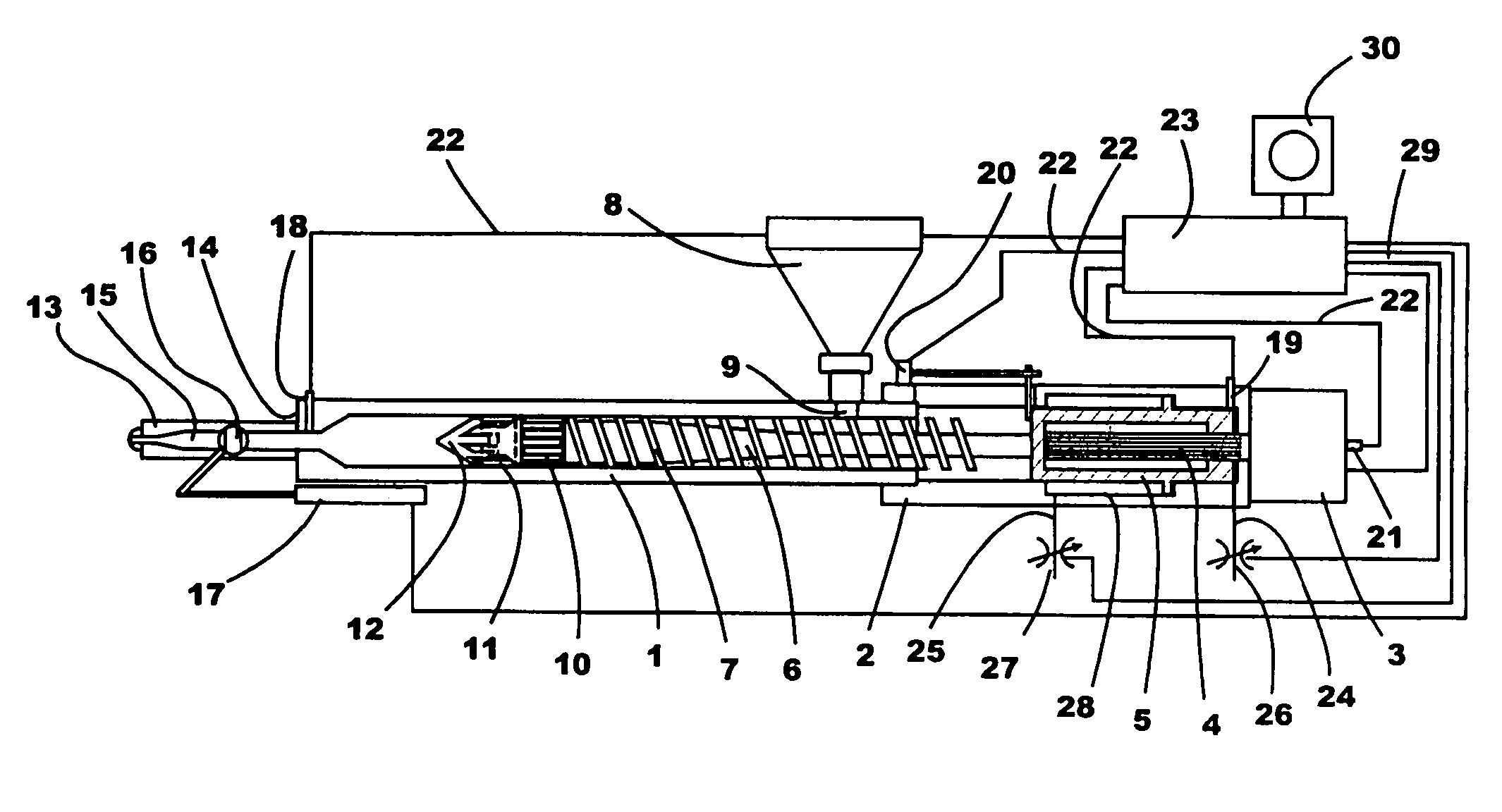
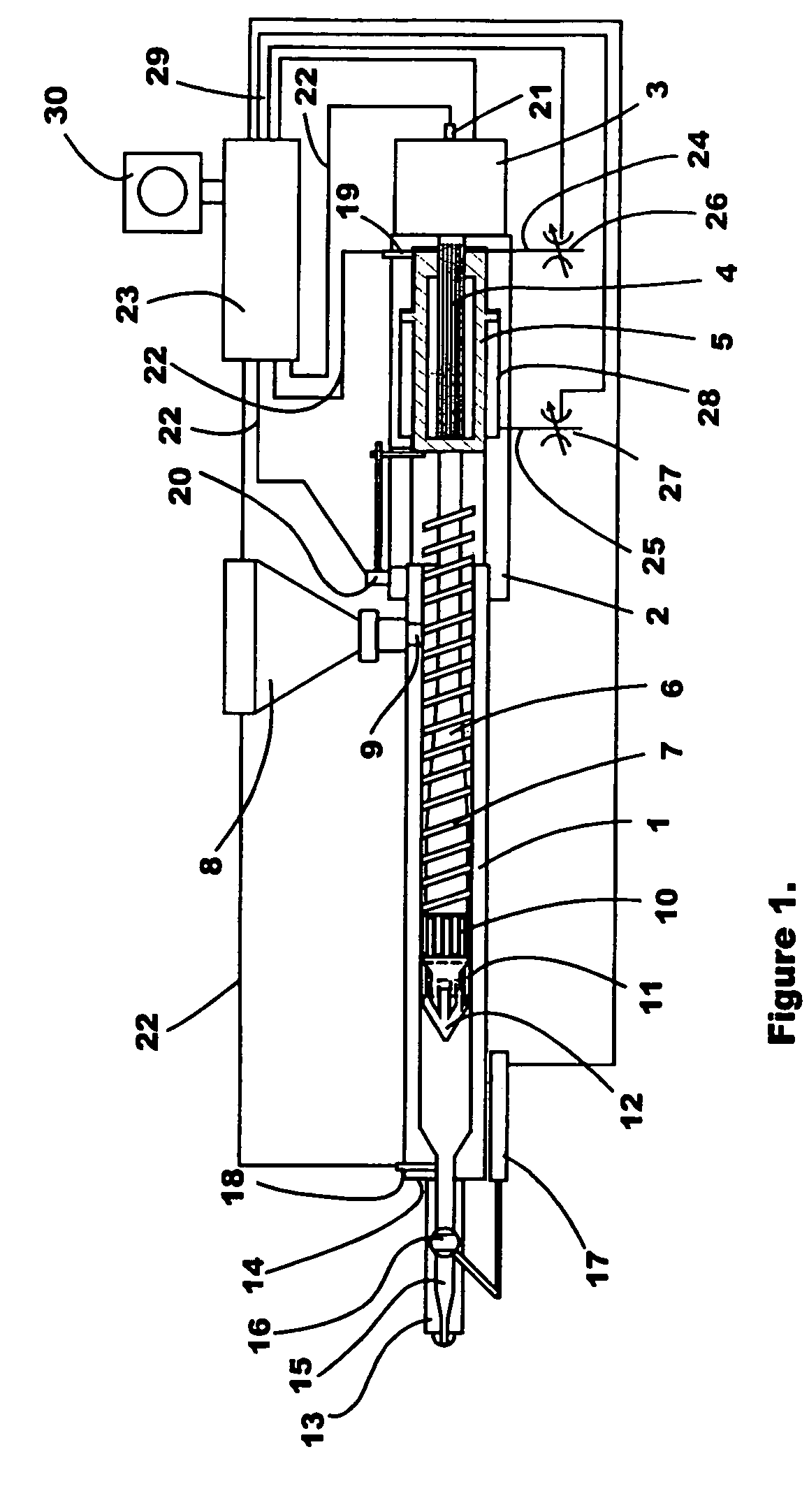
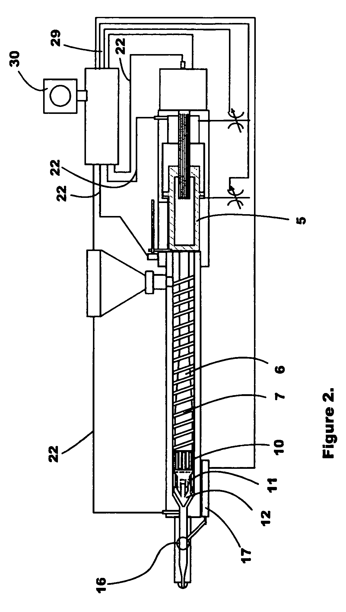
[0035]As discussed above, there is a need in the art for an RS injection unit apparatus and method that obviates a number of the problems noted above, and provides increased efficiency. There is further a need in the art for an injection unit apparatus and method that utilizes a screw with a non-return valve to inject and maintain hold pressure in a mold cavity, while the screw continues to rotate in a direction for plasticating resin without displacing resin for the next shot into a reservoir downstream of the screw. There is further a need for apparatus and methods for melting and mixing the resin between the flights of an injection screw without displacing that resin along said flights toward an open outlet at the screw tip. These needs are addressed by the apparatus and methods of the present invention described herein.

[0036]The concepts of the present invention will now be described with respect to an exemplary application in a plastic injection molding machine i...


PUM

PropertyMeasurementUnit
pressureaaaaaaaaaa
pressureaaaaaaaaaa
dwell timeaaaaaaaaaa

Abstract

In a reciprocating (RS) injection unit environment, as shown in FIG. 1, a controller of the injection unit is arranged to continuously rotate the screw during both conventional plasticizing operation and shot injection. In this way the RS unit is more efficient, utilizing less energy and producing greater resin output. The injection unit includes a non-return valve adjacent a nozzle, which non-return valve is either configured to rotate with the screw to reduce wear or presented as a ball check style noon-return valve. In an injection molding environment, the rotating screw includes flights that allow granules of resin to melt and mix in spaces between adjacent flights, but the flights are arranged substantially to inhibit excessive displacement of resin around the flights.

Description

BACKGROUND OF THE INVENTION[0001]1. Field of the Invention[0002]The present invention relates to a reciprocating screw (RS) injection unit and is particularly, but not exclusively, applicable to a method of operating such an RS injection unit in a plastic injection molding machine.[0003]2. Related Art[0004]In a conventional RS unit, a feedscrew is rotated intermittently, thereby limiting the amount of time available for plasticizing the next injection shot. The waiting time between driving operations is usually called the recovery time.[0005]During the injection phase of operation of a conventional RS injection unit, the non-rotating screw is advanced to inject the melt into the mold. As the flights of the screw pass under the open hopper feed throat, unmelted resin granules fall in between the flights, becoming available for plasticating when the screw resumes rotation. However, in some applications, such as those with high speed injection rates, the high speed translation of the s...

Claims


Application Information

Patent Timeline
Patent Type & Authority Patents(United States)
IPC IPC(8): B29C45/52B29C45/77B29C45/00B29C45/50
CPCB29C45/77B29C2945/76936B29C2945/76083B29C2945/7611B29C2945/76113B29C2945/76187B29C2945/762B29C2945/76307B29C2945/76498B29C2945/76545B29C2945/76568B29C2945/76591B29C2945/76598B29C2945/76605B29C2945/76665B29C2945/76688B29C2945/76765B29C2945/76785B29C2945/76859B29C2945/76006B29C45/50B29C45/48B29C45/46
Inventor WEATHERALL, DOUGLAS JAMESPARIS, ALEXANDRE EDOUARD RAOUL
Owner HUSKY INJECTION MOLDING SYST LTD
Why Eureka
Try Eureka