Eureka AIR delivers breakthrough ideas for toughest innovation challenges, trusted by R&D personnel around the world.

Monitor and method for sensing temperature differences

a technology of temperature difference and monitor, applied in the direction of fire alarms, instruments, fire alarm electric actuation, etc., can solve the problems of complex measurement of temperature difference within an electrical panel, temperature increase, and failure of such electrical equipment, and achieve the effect of conserving the battery powering the system

Active Publication Date: 2007-11-06
IRISS HLDG INC
View PDF3 Cites 12 Cited by
  • Summary
  • Abstract
  • Description
  • Claims
  • Application Information

AI Technical Summary

Benefits of technology

[0028]By employing apparatus and techniques of the foregoing type an improved equipment monitor is achieved. In one embodiment a plastic case is fitted with a thermistor that projects from the front and another thermistor that projects from the back. The back thermistor is designed to fit through a hole in an enclosure. This hole can either pre-exist or can be drilled in preparation for installation of the case. The case may be mounted by integral magnets, adhesives, or other simple fastening means.
[0029]This case will include appropriate circuitry for sensing the temperature difference sensed by the inside and outside thermistors. The disclosed embodiment will have a trio of LEDs: green for normal, yellow for exceeding a first threshold, and red for exceeding a second higher threshold. To conserve the battery powering the system the lights will blink, with the green blinking once every 20 seconds, yellow blinking twice as fast and the red blinking three times as fast.

Problems solved by technology

Failure of such electrical equipment is typically preceded by a temperature increase.
The temperature increase can be caused by excessive current, unbalanced load, oxidation or corrosion at contact surfaces, lossy contacts that generate heat, arcing, etc.
Measuring a temperature increase within an electrical panel is complicated by the fact that the temperature rise can be caused by equipment defects, or simply by a rise in the ambient temperature.
A disadvantage with measuring these temperature differences is the complexity associated with the equipment capable of performing such measurements.
Being relatively complex, such systems often consume a fair amount of power and are therefore often connected to utility power lines, which adds to the complexity of the installation.

Method used


Image

  • Monitor and method for sensing temperature differences
  • Monitor and method for sensing temperature differences
  • Monitor and method for sensing temperature differences

Examples


Embodiment Construction

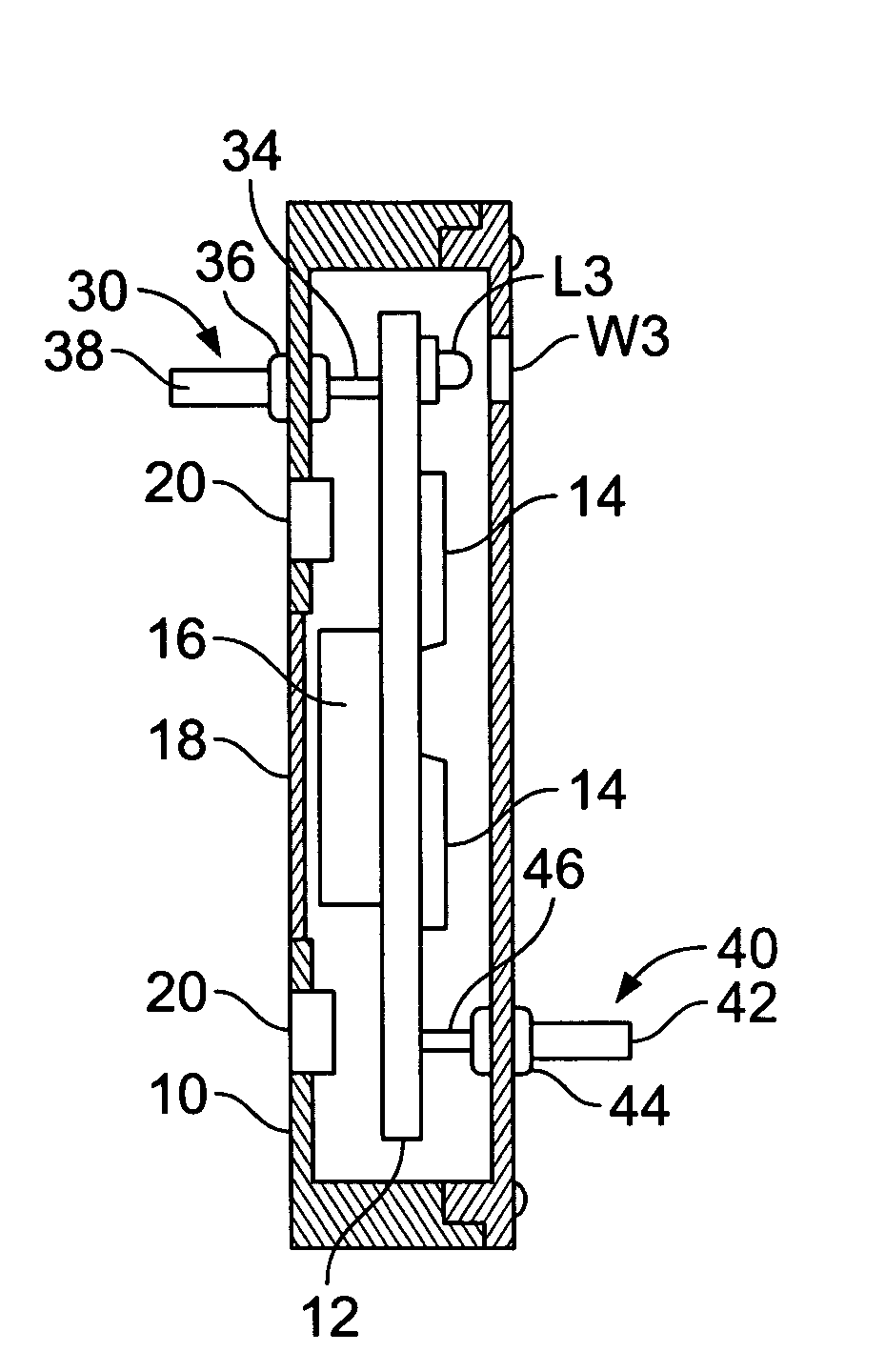
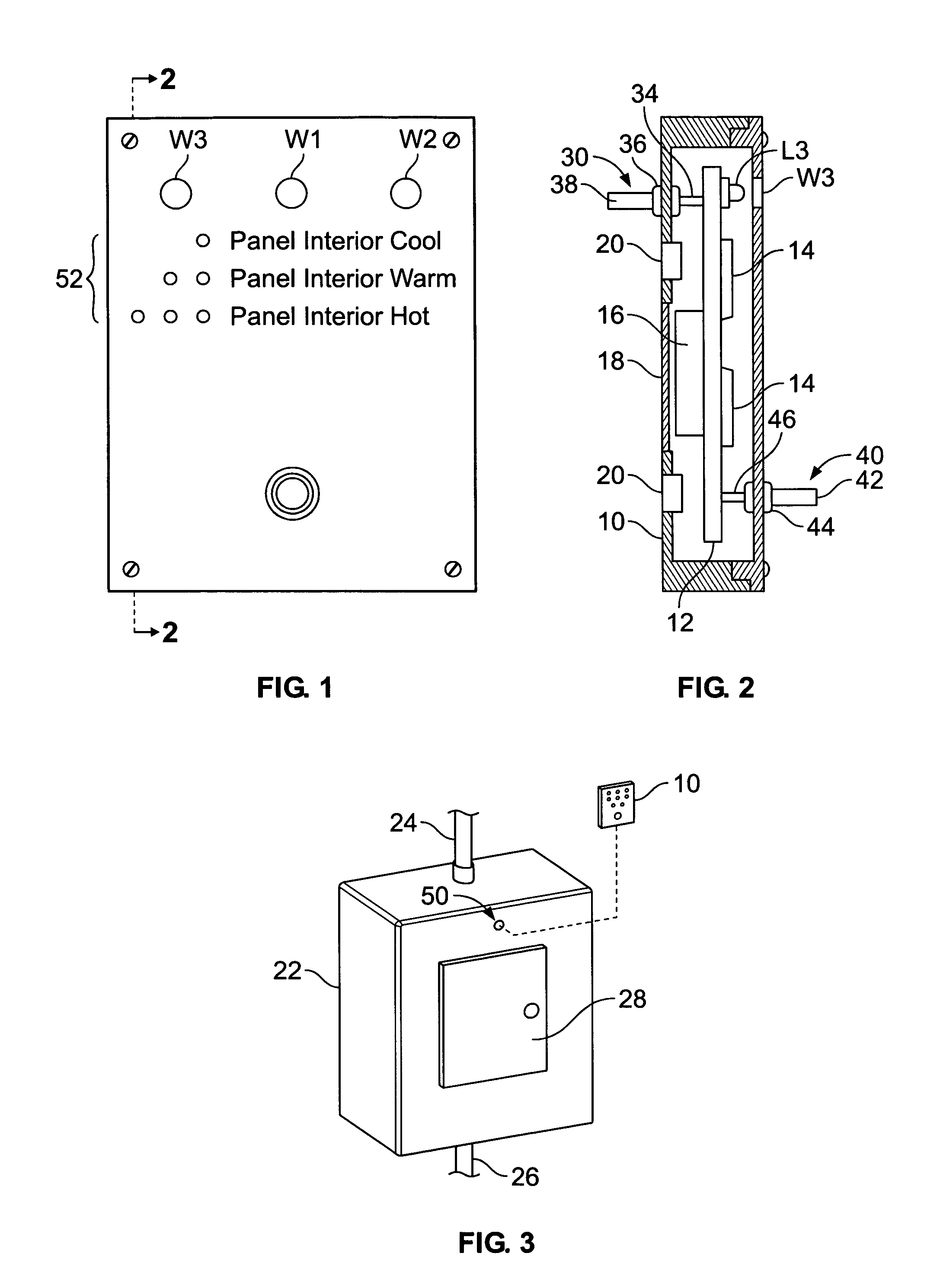
[0037]Referring to FIGS. 1 and 2, a monitor is shown as a case 10 containing a printed circuit board 12 with a number of integrated circuits 14 and a battery 16, all arranged to act as an alarm system. An access door 18 on the back of case 10 allows installation or replacement of battery 16. Mounted behind integral windows W1, W2, and W3 on circuit board 12 are a number of lights, one such light being shown herein as light emitting diode (LED) L3 mounted behind circular window W3 in the front of case 10.

[0038]Glued into openings in the back of case 10 are a pair of bar magnets 20 for magnetically securing case 10 to an enclosure made a steel or other ferromagnetic materials.

[0039]Referring to FIG. 3, an exemplary enclosure is shown as a power panel in the form of a steel box 22 into which are routed power lines 24 and 26. Door 28 can be opened to gain access to electrical power equipment inside box 22. Such equipment can be circuit breakers, contactors, relays, transformers, or othe...


PUM


Abstract

A monitor can sense the difference in temperature between the inside and the outside of an enclosure containing electrical power equipment. The monitor has a case adapted for mounting at the enclosure. Also included is a first and a second sensor for producing a first signal and a second signal, respectively. The first sensor is mounted at the case and is adapted for insertion through an opening in the enclosure. The second sensor is adapted to sense temperature at a location remote from the first sensor. Specifically, the case is mounted so that one of the sensors is inside the enclosure and the other is outside. The monitor also includes an alarm system mounted at the case and coupled to the first and the second sensor for producing a warning signal in response to the first and the second signals from the first and the second sensor signifying a temperature difference exceeding a predetermined threshold.

Description

BACKGROUND OF THE INVENTION[0001]1. Field of the Invention[0002]The present invention relates to apparatus and techniques for detecting the temperature differential existing around various electrical power equipment and enclosures.[0003]2. Description of Related Art[0004]Residential, commercial, and industrial buildings typically have electrical panels in the form of a box or covered recess that may contain circuit breakers, power contactors, relays, fuses or other equipment designed to deliver or route primary utility current to locations in the building. Failure of such electrical equipment is typically preceded by a temperature increase. The temperature increase can be caused by excessive current, unbalanced load, oxidation or corrosion at contact surfaces, lossy contacts that generate heat, arcing, etc.[0005]Measuring a temperature increase within an electrical panel is complicated by the fact that the temperature rise can be caused by equipment defects, or simply by a rise in t...

Claims


Application Information

Patent Timeline
Patent Type & Authority Patents(United States)
IPC IPC(8): G08B17/00
CPCG08B17/06G08B17/00G08B17/113
Inventor BAIER, FREDERICK A.BARTON, CHRISTOPHERCHAPMAN, STEPHEN
Owner IRISS HLDG INC
Why Eureka
Eureka Blog
Learn More