Contained resonant cavity and systems incorporating same

a cavity and resonant technology, applied in the field of cavity for manipulating electromagnetic energy, can solve the problems of increasing the price and design complexity of systems employing etalons, affecting the performance of filters, and prohibitively lossy filters for many applications, so as to reduce the requirements of parallelism, smoothness, and reflection

Inactive Publication Date: 2007-11-06
TANNER RES
View PDF2 Cites 3 Cited by
  • Summary
  • Abstract
  • Description
  • Claims
  • Application Information

AI Technical Summary

Benefits of technology

[0017]The novel design of one embodiment of the present invention is facilitated by the substantially reflective sidewalls extending between the partially reflective and transmissive input and output surfaces, thereby forming a unique contained cavity adapted to resonate electromagnetic energy. The sidewalls prevent walk off of electromagnetic energy within the cavity, thereby facilitating various applications including optical filter arrays, multispectral imaging systems, lens-less imaging systems, resonant-cavity-enhanced photodiodes, and tunable lasers. Use of the reflective sidewalls further reduces reflectivity, smoothness, and parallelism requirements for the input and output surfaces of the contained resonant cavities.

Problems solved by technology

Otherwise, power loss due to the walk-off effect and absorption may be problematic.
Stringent requirements for Fabry-Perot etalons increase the price and design complexity of systems employing the etalons.
Unfortunately, the walk-off effect causes such filters to be prohibitively lossy for many applications.
Furthermore, Fabry-Perot etalons typically exhibit resonance at discrete wavelengths only, which limits applicability of the etalons.

Method used


Image

  • Contained resonant cavity and systems incorporating same
  • Contained resonant cavity and systems incorporating same
  • Contained resonant cavity and systems incorporating same

Examples


Embodiment Construction

[0031]While the present invention is described herein with reference to illustrative embodiments for particular applications, it should be understood that the invention is not limited thereto. Those having ordinary skill in the art and access to the teachings provided herein will recognize additional modifications, applications, and embodiments within the scope thereof and additional fields in which the present invention would be of significant utility.

[0032]The following review of a conventional Fabry-Perot resonant cavity is intended to facilitate an understanding of the present invention.

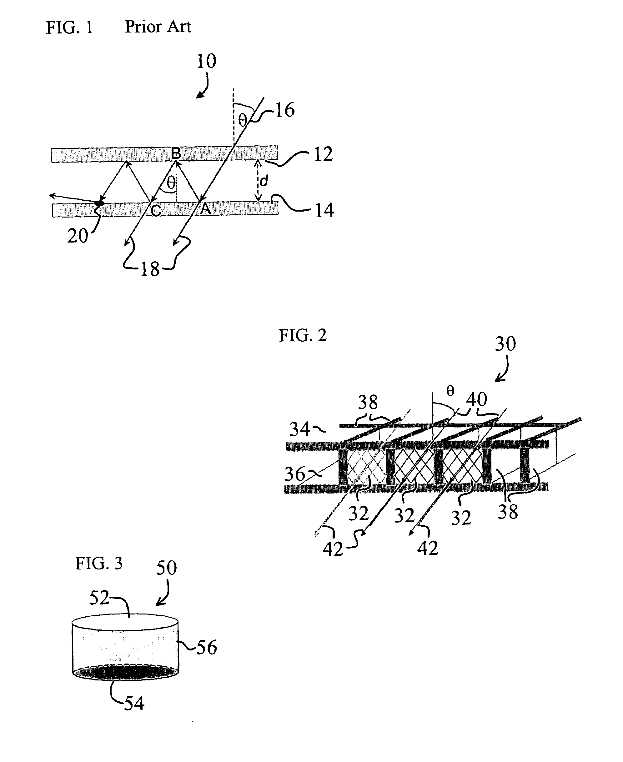
[0033]FIG. 1 is a diagram illustrating the walk-off effect in a conventional Fabry-Perot resonant cavity 10. The resonant cavity 10 is formed between a first mirror 12 and a second mirror 14, which are partially reflective and partially transmissive and which are substantially parallel. The first mirror 12 provides an input surface for incident electromagnetic energy 16, while the second mirror 1...


PUM

PropertyMeasurementUnit
refractive indexaaaaaaaaaa
separation distanceaaaaaaaaaa
thickaaaaaaaaaa

Abstract

A contained resonant cavity. The contained resonant cavity includes a first surface and a second surface that are partially transmissive and partially reflective, One or more reflective sidewall, are positioned between the first surface and the second surface. In a specific embodiment, the first surface and the second surface are substantially parallel and represent input and output surfaces, respectively, of the contained resonant cavity. The one or more sidewalls are approximately perpendicular to the first surface and the second surface and include a first sidewall having a first substantially reflective planar surface that faces a second substantially reflective planar surface of the second sidewall. A third sidewall and a fourth sidewall have fourth and fifth substantially reflective Lacing sidewalls, respectively. In an illustrative embodiment, the one or more sidewalls include plural reflective sidewall, arranged perpendicularly between the first surface and the second surface to form an array of contained resonant cavities therebetween. The ray of contained resonant cavities is readily employed in various applications including unique tunable optical filter rays, lens-less imaging systems, and multispectral imaging systems.

Description

CLAIM OF PRIORITY[0001]This application claims priority from U.S. Provisional Patent Application Ser. No. 60 / 481478, filed Oct. 7, 2003, entitled TUNABLE OPTICAL FILTER ARRAYS, ENHANCED HYPERSPECTRAL FOCAL PLANE ARRAYS, LENS-LESS IMAGING SYSTEMS AND OTHER DEVICES BASED ON CONTAINED RESONANT CAVITIES, which is incorporated by reference herein.ACKNOWLEDGEMENT OF GOVERNMENT SUPPORT[0002]This invention was made with Government support under Contract No.s: DASG6003-P-0056, DASG60-03-P-0059, and NAS1-03032 awarded by the United States Department of Defense Small Business Innovation Research (SBIR) Program. The Government may have certain rights to this invention.BACKGROUND OF THE INVENTION[0003]1. Field of Invention[0004]This invention relates to cavities for manipulating electromagnetic energy. Specifically, the present invention relates to resonant cavities and accompanying systems.[0005]2. Description of the Related Art[0006]Resonant cavities are employed in various demanding applicati...

Claims


Application Information

Patent Timeline
Patent Type & Authority Patents(United States)
IPC IPC(8): G02F1/03G01B9/02G02B26/00
CPCG02B26/001
Inventor VERMA, RAVISIVILOTTI, MASSIMO A.EMERLING, MICHAEL
Owner TANNER RES
Why Eureka
Try Eureka