Al technical title is built by PatSnap Al team. It summarizes the technical point description of the patent document.
a technology for umbrellas and operating systems, applied in tents/canopies, building types, constructions, etc., can solve problems such as potential damage to mounted canopy frames, and achieve the effect of convenient manipulation
Inactive Publication Date: 2007-11-13
TUUCI WORLDWIDE LLC
View PDF39 Cites 56 Cited by
Summary
Abstract
Description
Claims
Application Information
AI Technical Summary
This helps you quickly interpret patents by identifying the three key elements:
Problems solved by technology
Method used
Benefits of technology
[0011]The present invention is designed to address these and other needs which remain in the art and relates primarily to a durable outdoor umbrella frame structured to allow the umbrella to be easily opened and adjusted to various desired positions and then reliably maintained in place. Accordingly, and as explained more in detail subsequently herein, the present invention includes at least one hub member mounted to an umbrella pole member and slidable between the top and bottom ends thereof. In a preferred embodiment, the invention comprises a pair of hub members, namely, one secured to the pole member near the top end thereof and a main hub member movably secured about the pole member and slidable therealong to open and close the umbrella canopy. In addition, the hub members are preferably mounted on the umbrella pole member so as to both be rotatable about the pole, and to generally assist in the smooth operation of the umbrella frame. In this most preferred embodiment, the hub members are easily mounted to and can be easily removed from the umbrella pole member for repair and / or for replacement, if necessary. Further, the hub members ideally are of a type structured to include a plurality of slots about their radial edges for receiving a combination of hub connector joints. A matching number of ribs and struts are pivotally secured to each hub by these joints, and the struts are pivotally secured to the ribs by collar members as shown in at least one illustrated embodiment. The hub connector joints and the collar members are easily mounted and replaced, and also assist in the smooth operation of the umbrella frame. Additionally, the collar members maintain a low profile so as to avoid contacting and thereby potentially damaging a mounted canopy.
[0012]The present invention also provides a versatile umbrella operating system which allows an umbrella to be safely and easily opened to almost any degree, easily rotated, and securely stabilized. As such, the present invention includes an operating system to allow the umbrella to be easily adjusted to almost any degree of openness and simply locked or otherwise maintained in place. In one embodiment, the operating system comprises but is not limited to a pulley system connecting or interconnected with the hub members and structured to move the main hub member up and down a length of the pole towards the top end of the pole, preferably relative to a top hub member disposed at the top of the pole. The operating system may include a stabilizer arm to achieve the opening and / or closing of the umbrella and / or to bolster support to the umbrella and provide a safer, more effective way to lock and unlock the umbrella in its fully extended position.
Problems solved by technology
Additionally, the collar members maintain a low profile so as to avoid contacting and thereby potentially damaging a mounted canopy.
Method used
Image
Click on the blue label to locate the original text in one second.
Reading with bidirectional positioning of images and text.
Examples
Embodiment Construction
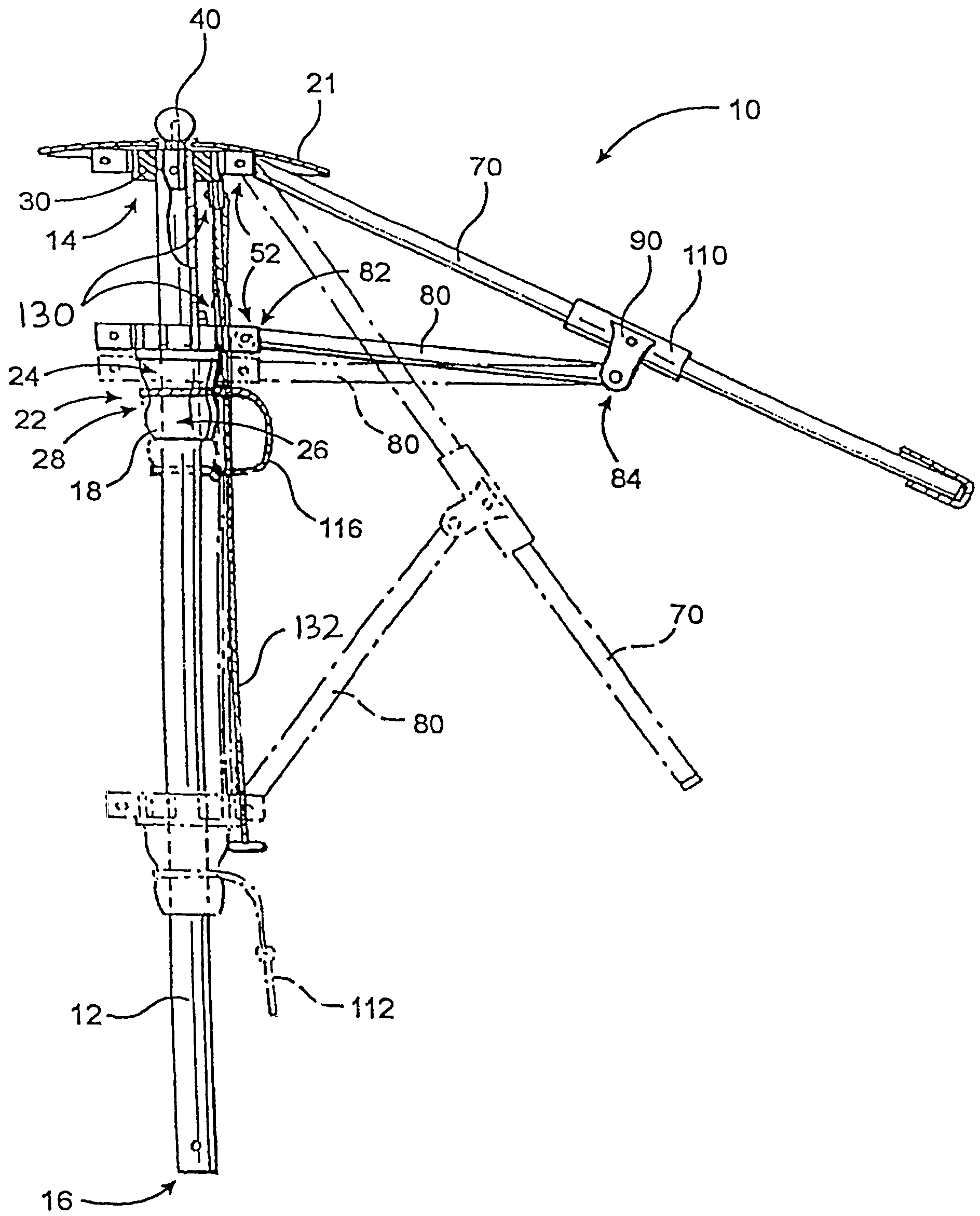
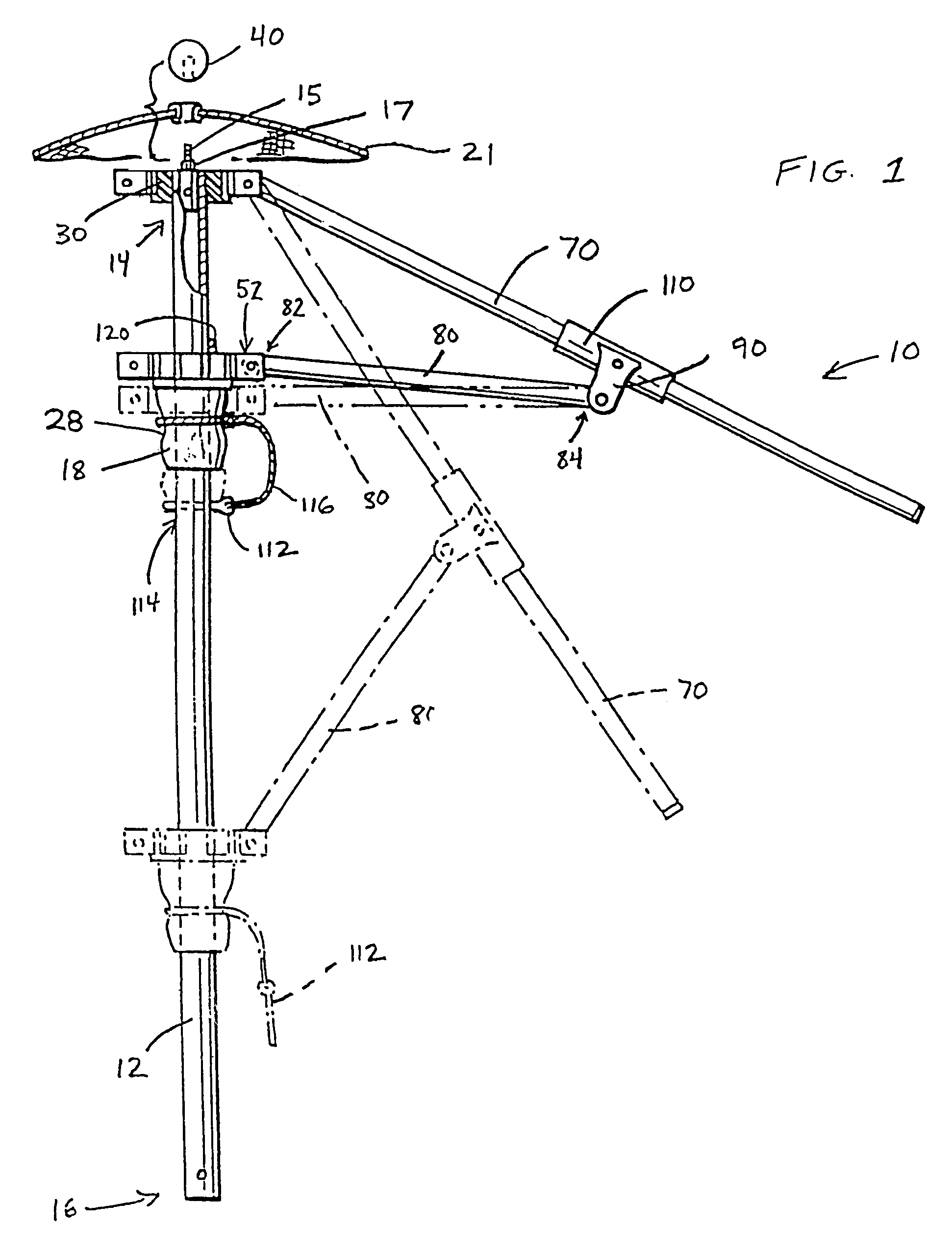
[0034]As shown throughout the various Figures, the present invention relates to an improved umbrella frame and operating assembly.
[0035]With initial reference to FIGS. 1 through 8, an improved umbrella frame assembly, generally indicated by reference numeral 10, according to the present invention will now be described. The umbrella frame assembly 10 is intended for use in easily and quickly supporting a variety of shapes and sizes of umbrella canopies, and is structured to be both durable and weather resistant. As illustrated in these Figures, the frame assembly 10 includes a longitudinally extending pole member 12 which can be made of wood, aluminum or other material. In one embodiment, the pole member 12 is made of 40 gauge aluminum. The pole member 12 has a top end 14 and a bottom end 16. The bottom end 16 may be easily secured to the ground or any means of vertical affixment, such as but not limited to a reinforced concrete base, which for example, might have a star knob and hit...
PUM
Abstract
An improved, durable and versatile umbrella frame assembly is provided to more readily endure abusive weather conditions and that may be quickly, easily and inexpensively repaired. In addition, the assembly is also easily modified to accommodate umbrella canopies of different sizes and shapes. In addition, an improved umbrella operating system is provided to permit simple opening, positioning, and locking of an umbrella while allowing the frame to freely rotate about the pole regardless of the degree to which it is opened, while the pole is held in a stationary position. The assembly includes a pair of hub members mounted about a pole member wherein the main hub member is slidable up and down the pole. A pulley system with a locking cam member may be employed to allow the umbrella to safely and easily open to any desired position. A locking stabilizer arm may be used to secure the main hub member in the fully open position.
Description
CLAIM OF PRIORITY[0001]This is a continuing patent application based on a U.S. patent application having Ser. No. 10 / 008,536, which was filed on Nov. 13, 2001 now U.S. Pat. No. 6,889,699 and which is a continuation-in-part patent application of a prior-filed U.S. patent application, namely, Ser. No. 09 / 330,600 which was filed on Jun. 11, 1999 and which matured into U.S. Pat. No. 6,314,976 on Nov. 13, 2001, and also of another prior-filed U.S. patent application, namely, Ser. No. 09 / 433,881 which was filed on Nov. 4, 1999 and which matured into U.S. Pat. No. 6,386,214 B1 on May 14, 2002, all of which are incorporated herein in their entirety, by reference.BACKGROUND OF THE INVENTION[0002]1. Field of the Invention[0003]This invention relates generally to umbrellas, and more particularly, to a durable and versatile umbrella frame designed to more readily endure abusive weather conditions. The present invention also relates more specifically to an umbrella operating system having improv...
Claims
Application Information
Patent Timeline
Application Date:The date an application was filed.
Publication Date:The date a patent or application was officially published.
First Publication Date:The earliest publication date of a patent with the same application number.
Issue Date:Publication date of the patent grant document.
PCT Entry Date:The Entry date of PCT National Phase.
Estimated Expiry Date:The statutory expiry date of a patent right according to the Patent Law, and it is the longest term of protection that the patent right can achieve without the termination of the patent right due to other reasons(Term extension factor has been taken into account ).
Invalid Date:Actual expiry date is based on effective date or publication date of legal transaction data of invalid patent.