Semiconductor device

a technology of semiconductor devices and films, applied in semiconductor devices, semiconductor/solid-state device details, radiation control devices, etc., can solve the problems of not being able to form whole dummy vias, not being able to place the dummy via that connects interconnects respectively formed, and having different electric potentials, so as to improve the adhesiveness of films, and increase the effect of an additional process

Active Publication Date: 2007-11-13
RENESAS ELECTRONICS CORP
View PDF3 Cites 18 Cited by
  • Summary
  • Abstract
  • Description
  • Claims
  • Application Information

AI Technical Summary

Benefits of technology

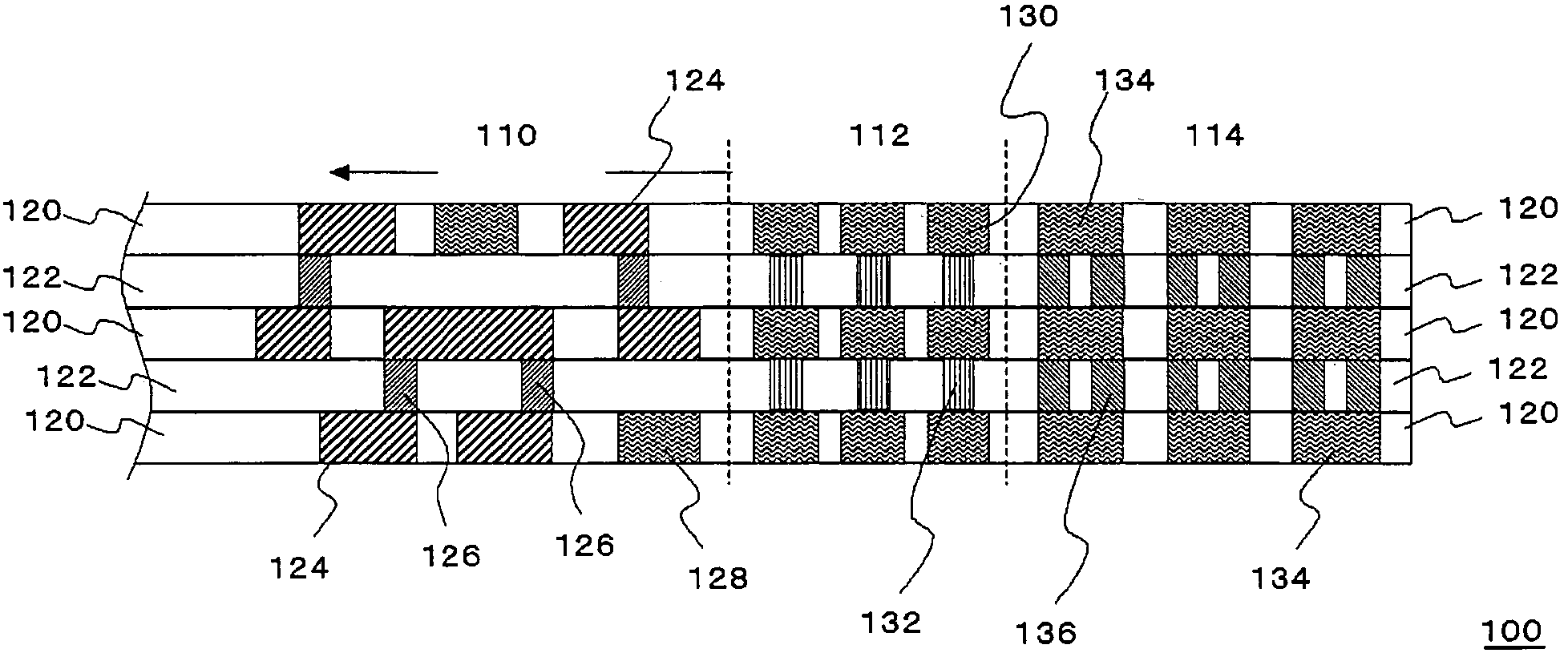
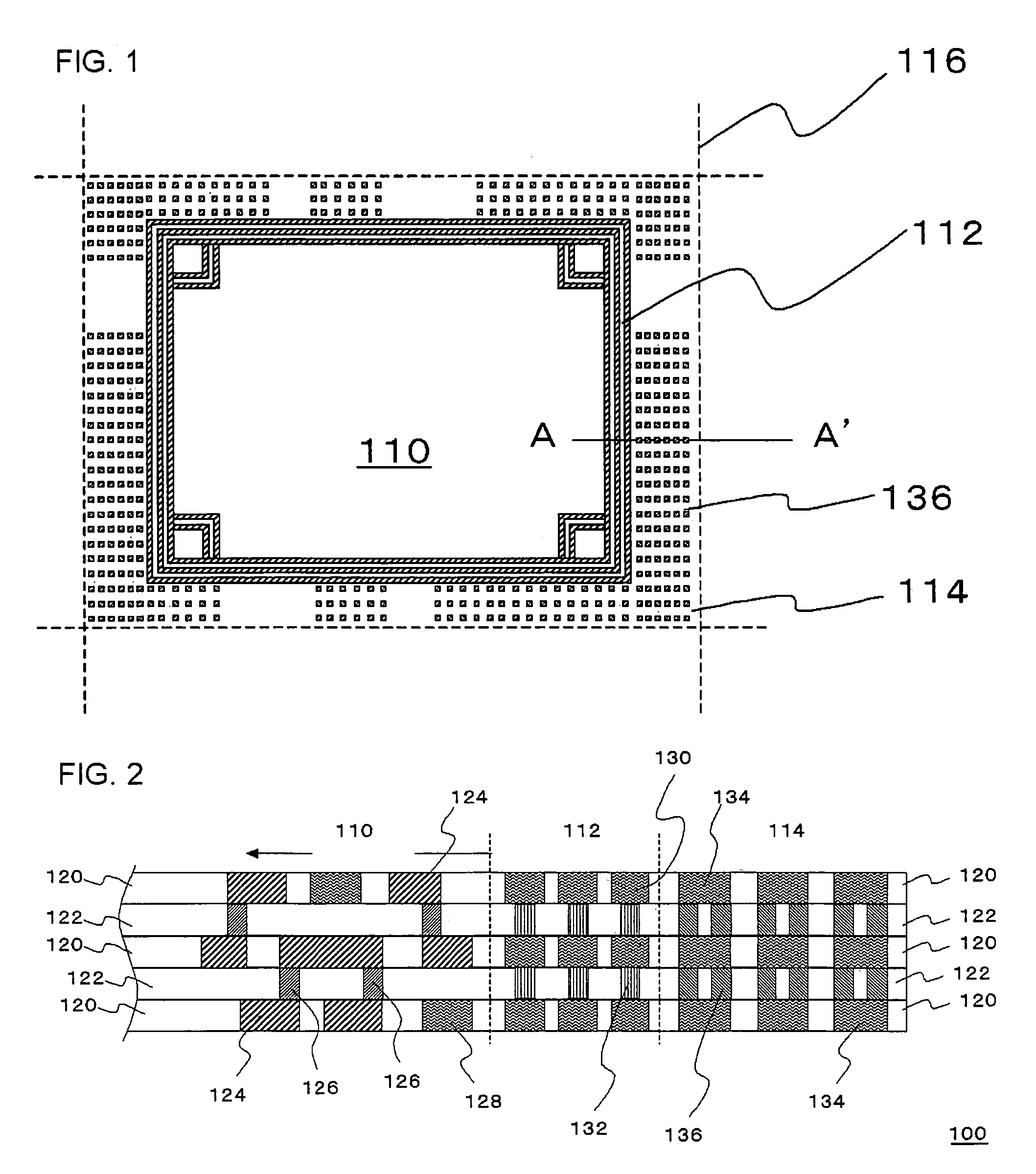
[0012]By introducing the dummy via formed of a metal material in the second interlayer dielectric film, the second interlayer dielectric film can be strengthened. Furthermore, as the dummy via functions as a wedge or connection between the films, the adhesiveness of the films can be improved as well.
[0030]According to the present invention, the adhesiveness between films in the multilayer wiring structure can be improved.

Problems solved by technology

As there are formed register marks at the peripheral region, not like the seal rings, it is not possible to form the dummy vias whole regions of the peripheral region.
However, as for the dummy vias in the second interlayer dielectric film, it is impossible to place the dummy via that connects interconnects respectively formed in films placed above and below the second interlayer dielectric film and set to have different electric potentials.
With this reason, it is difficult to introduce the dummy vias at the circuit region in the second interlayer dielectric film without having the size of the semiconductor device large.

Method used


Image

  • Semiconductor device
  • Semiconductor device
  • Semiconductor device

Examples


example

[0061]A semiconductor chip, size of which is 20 mm×20 mm, having a multilayer wiring structure of nine layers and copper interconnects in which low-dielectric-constant insulating films (SiOC) having the relative dielectric constant of 2.3 are used as the interlayer dielectric film was obtained. In the semiconductor chip, the dummy vias were provided at the peripheral region thereof where the content rate of metals in the region was 11%. At the same time, a reference semiconductor chip having the same structure as described above but no dummy vias were provided was obtained.

[0062]To each of the semiconductor chips, heat cycles from −60 to 150 degree centigrade were applied for a thousand (1,000) times. As a result, almost no peeling-off of the films was seen on the semiconductor chip with the dummy vias. On the contrary, as for the reference semiconductor chip without the dummy vias, peeling-off of the films was seen to the extent of no less than 80%.

[0063]While the preferred embodim...


PUM


Abstract

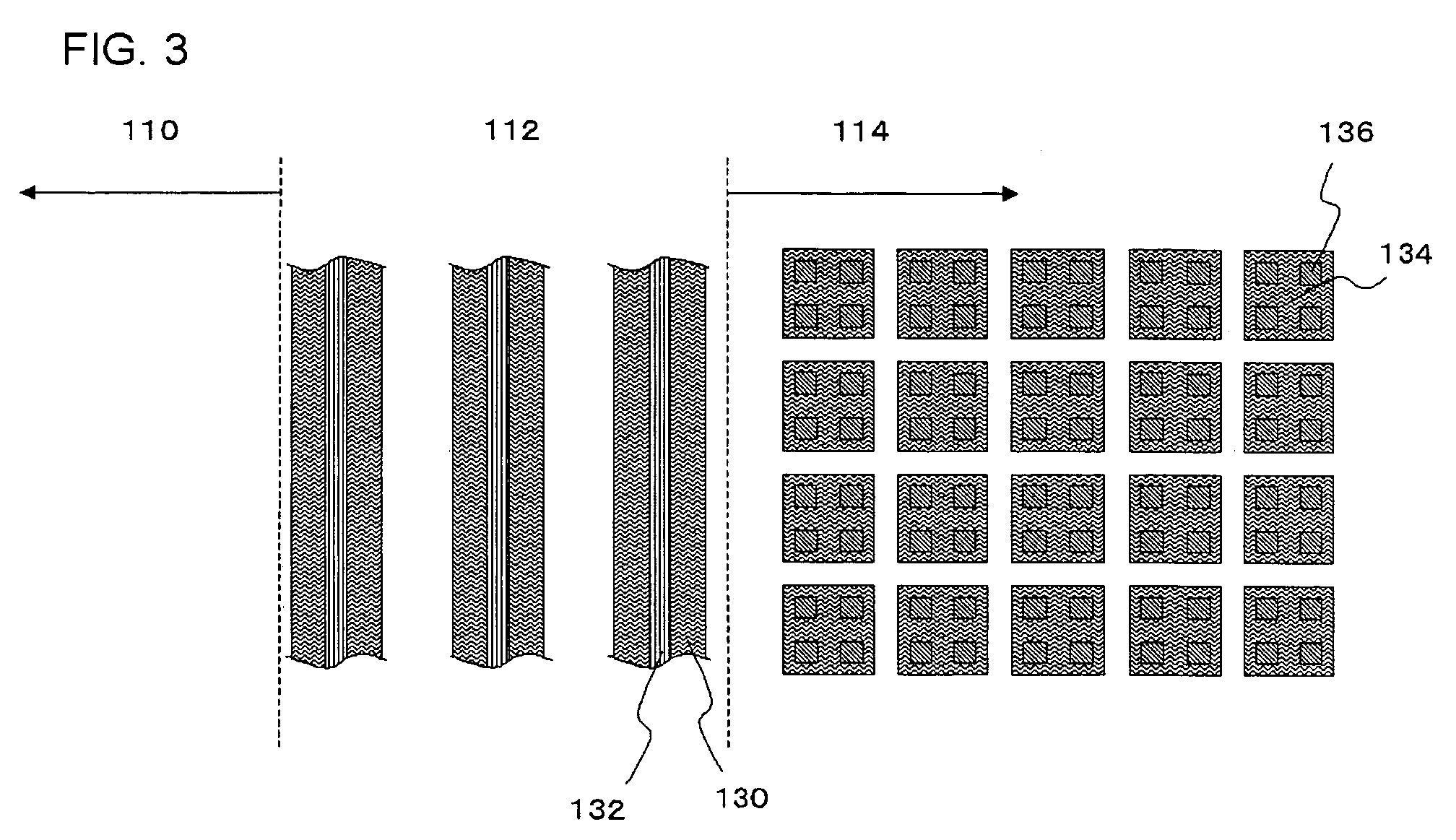
The semiconductor device 100 includes a multilayer wiring structure formed on the semiconductor substrate. The multilayer wiring structure includes at least a first inter layer dielectric film 120 in which interconnects 124 are formed, and at least a second inter layer dielectric film 122 in which vias 126 are formed. The multilayer wiring structure includes a circuit region 110 in which the interconnects 124 and the vias 126 are formed, a seal ring region 112 formed around the circuit region 110 and in which seal rings surrounding the circuit region 110 in order to seal the circuit region 110 are formed, and a peripheral region 114 formed around the seal ring region 112. The semiconductor device 100 further includes dummy vias 136 formed of a metal material, formed in the second interlayer dielectric film 122 at the peripheral region 114.

Description

[0001]This application is based on Japanese patent application NO. 2004-220073, the content of which is incorporated hereinto by reference.BACKGROUND OF THE INVENTION[0002]1. Field of the Invention[0003]The present invention relates to a semiconductor device including a multilayer wiring structure.[0004]2. Related Art[0005]With recent demands on faster operation speed of semiconductor devices, a great deal of investigational efforts have been made on alteration of an insulating interlayer from conventional silicon oxide film (dielectric constant K=4.3 or around) to a low-dielectric-constant insulating material layer, in order to reduce the inter-wiring capacitance. Examples of the low-dielectric-constant insulating materials include HSQ, MSQ, carbon-containing silicon oxide material and aromatic-group-containing organic resin material those having a dielectric constant of 3 or around. In pursuit of further reduction in the dielectric constant, recent developmental efforts are also m...

Claims


Application Information

Patent Timeline
Patent Type & Authority Patents(United States)
IPC IPC(8): H01L23/48
CPCH01L21/76801H01L21/7684H01L21/76838H01L21/78H01L23/522H01L23/5226H01L23/585
Inventor HIROI, MASAYUKI
Owner RENESAS ELECTRONICS CORP
Why Eureka
Try Eureka