Method and apparatus for coding image information, method and apparatus for decoding image information, method and apparatus for coding and decoding image information, and system of coding and transmitting image information

a technology of image information and coding method, which is applied in the field of coding image information, can solve the problems of mpeg2 standard not supporting coding at lower bit rate, coding with very high compression ratios is not supported by mpeg2 standard, and quantization accuracy is limited to the range of 8 to 10 bits

Active Publication Date: 2007-11-13
SONY CORP
View PDF4 Cites 54 Cited by
  • Summary
  • Abstract
  • Description
  • Claims
  • Application Information

AI Technical Summary

Benefits of technology

[0116]In the first image information decoding apparatus, an array B(QP) consisting of elements having values which increase or decrease by β % with increasing of the value of the parameter QP by 1 may be used as the sequence of numbers corresponding to the quantization step sizes, and the dequantization may be performed by multiplying the quantized coefficients by the values of the array B(QP).
[0117]In the first image information decoding apparatus, when the parameter QP exceeds an upper limit or a lower limit, the array B(QP) may be extended so as to have an extended value or values determined on the basis of the increasing

Problems solved by technology

The MPEG2 standard has been designed to code image information with high quality for use mainly in broadcasting, and the MPEG2 standard does not support coding at lower bit rates (higher compression rates) than are supported by the MPEG1 standard.
That is, coding with very high compression ratios is not supported by the MPEG2 standard.
However, the highest quantization accuracy is allowed only in the 4:2:2: format, and the quantization accuracy is limited to the range from 8 to 10 bits except for the high profile for use

Method used


Image

  • Method and apparatus for coding image information, method and apparatus for decoding image information, method and apparatus for coding and decoding image information, and system of coding and transmitting image information
  • Method and apparatus for coding image information, method and apparatus for decoding image information, method and apparatus for coding and decoding image information, and system of coding and transmitting image information
  • Method and apparatus for coding image information, method and apparatus for decoding image information, method and apparatus for coding and decoding image information, and system of coding and transmitting image information

Examples


first embodiment

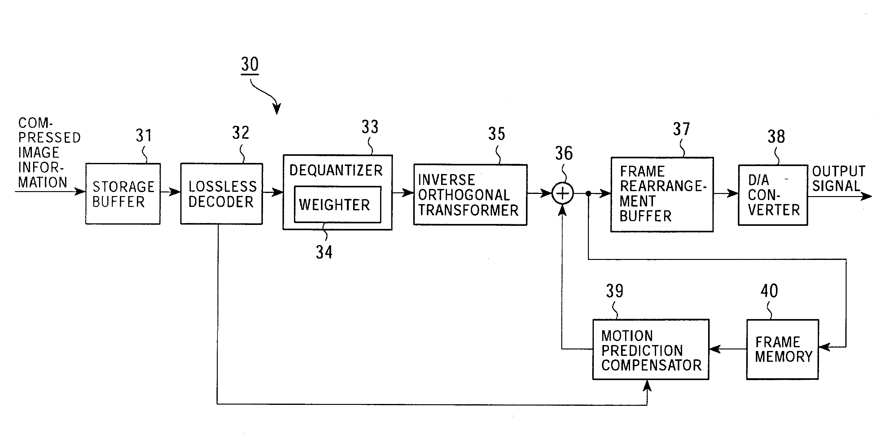
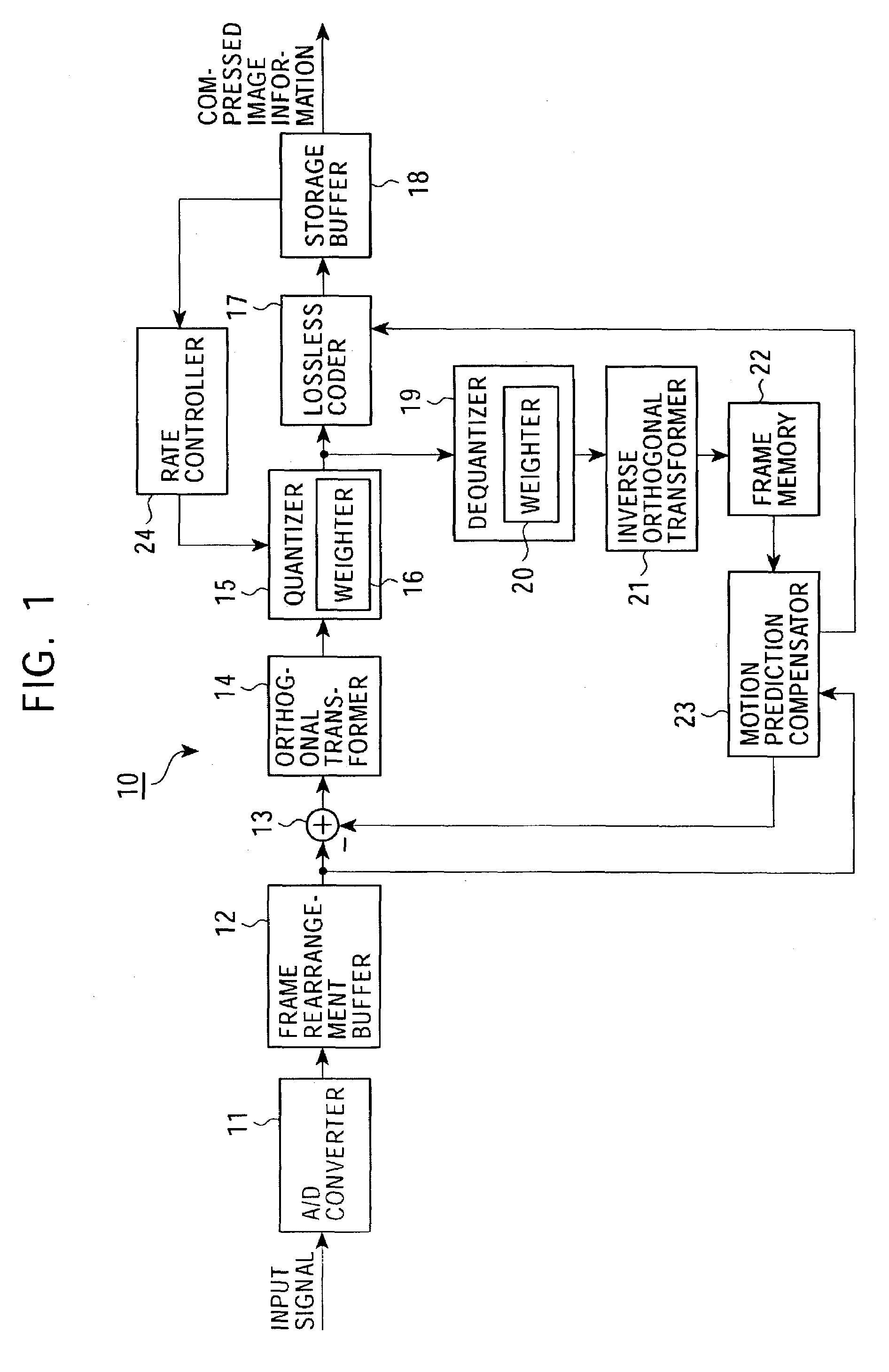
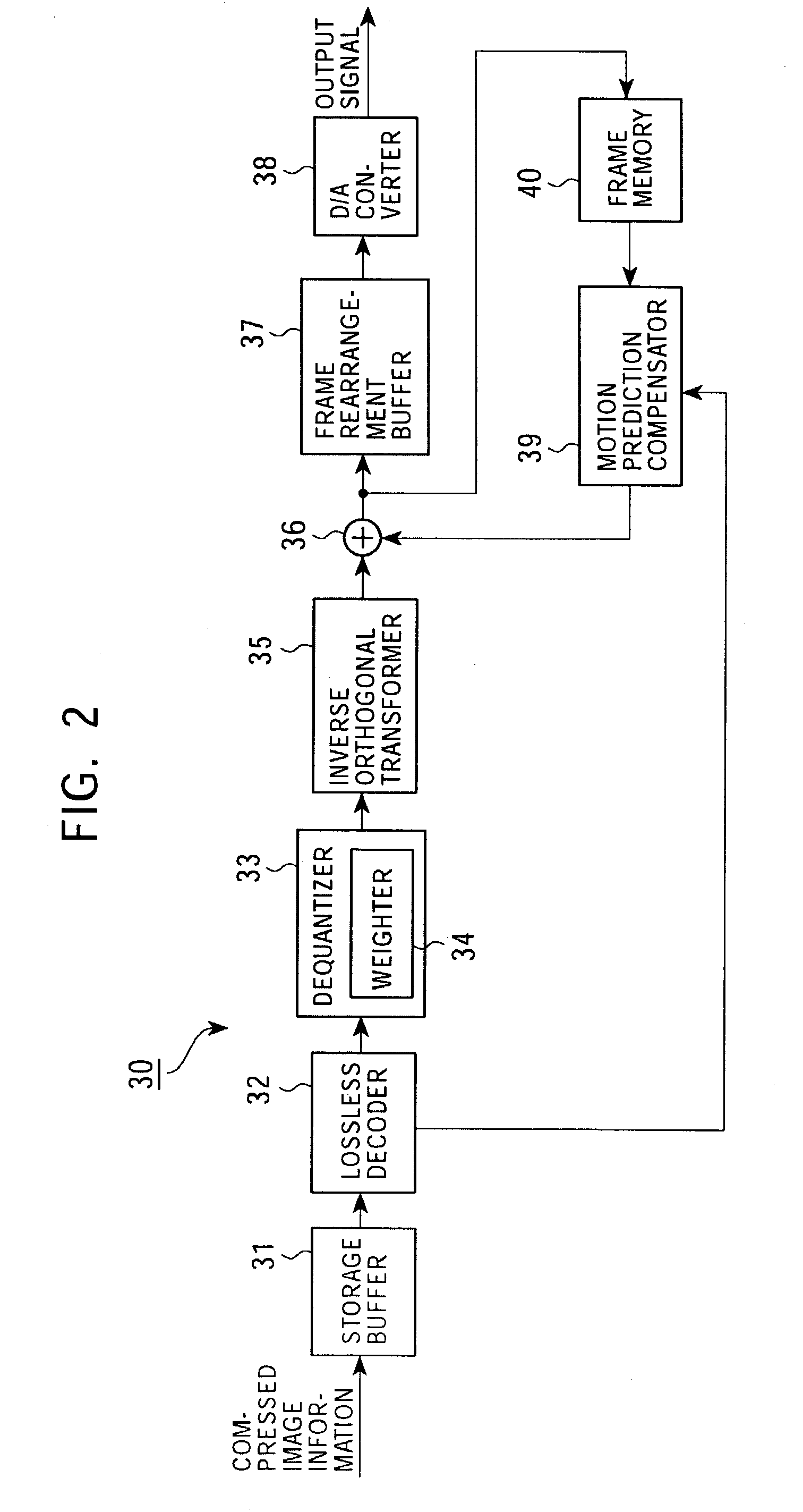
[0210]As a first embodiment of the present invention, an image signal coder for producing compressed image information by dividing an input image signal into blocks, performing an orthogonal transform on the blocks on a block-by-block basis, and quantizing resultant orthogonal transform coefficients, and an image signal decoder for decoding coded image information by dequantizing it and performing an inverse transform are described.

[0211]In the image information coding apparatus and the image information decoding apparatus according to the present embodiment, as will be described in detail later, weighting is performed on a parameter specifying one of elements of a sequence of numbers arranged in accordance with a predetermined rule in correspondence to quantization step sizes thereby making it possible to use greater quantization step sizes in quantizing orthogonal transform coefficients in a high frequency range in which the great quantization step sizes does not result in signifi...

first modification

[0291]In the first embodiment described above, two arrays A(QP) and B(QP) are given in the form of tables. Alternatively, two arrays A(QP) and B(QP) may be determined in accordance with equations as described below.

[0292]For example, arrays A(QP) and B(QP) may be given by equations (21) and (22), respectively.

A(QP)=Amantissa(QP)·2Aexponent(QP)  (21)

B(QP)=Bmantissa(QP)·2Bexponent(QP)  (22)

[0293]In the above equations ((21) and (22)), array A(QP) is set such that the values of elements thereof decrease by 12% with increasing of the value of QP by 1, the values of elements of array A(QP) is approximately halved each time the value of QP increases by 6. Thus, if Amantissa(QP) is defined for first six values of QP in equation (21), then array A(QP) can be extended such that any set of six elements are produced by multiplying a previous set of six elements by ½ as shown in equation (23).

{a1, a2, a3, a4, a5, a6},

[0294]{a7⁡(=a12),a8⁡(=a22),a9⁡(=a32),a10⁡(=a42),a11⁡(=a52),a12⁡(=a62)},(23)

[02...

second modification

[0301]In H.26L (JVT Codec), 4×4-size orthogonal transform and quantization are performed on 16 DC components of a luminance signal in a macroblock to be intra-coded, and 2×2-size orthogonal transform and quantization are performed on 4 DC components of color difference signals in the macroblock to be intra-coded. The orthogonal transform is not limited to the discrete cosine transform employed in the present embodiment, but other orthogonal transforms such as an Hadamard transform may also be employed.

[0302]In the quantization of DC components of the luminance signal and the color difference signal, a weighting matrix W(i, j) different from that applied to AC components may be employed as described below.

[0303]For example, in the case in which the Hadamard transform is employed, a 4×4-size Hadamard transform is represented by equation (35).

[0304](111111-1-11-1-11111-1)(35)

[0305]W(i, j) used in quantization after completion of the Hadamard transform is defined in a similar manner to ...


PUM


Abstract

An image information coding apparatus codes an input image signal in a manner optimized on the basis of the visual characteristics. In quantization, an input image signal is divided into blocks, an orthogonal transform is performed on a block-by-block basis, and resultant orthogonal transform coefficients are quantized. A quantizer includes a weighter for, in the quantization, performing weighting on each component of the orthogonal transform coefficients by means of an addition operation on a parameter specifying one of elements of a series of numbers arranged in accordance with a predetermined rule in correspondence with quantization step sizes.

Description

BACKGROUND OF THE INVENTION[0001]1. Field of the Invention[0002]The present invention relates to a method and apparatus for coding image information, a method and apparatus for decoding image information, a method and apparatus for coding and decoding image information, and a system for coding and transmitting image information, for use in receiving, via a network medium such as satellite broadcasting, cable television, or the Internet, image information (bit stream) compressed by means of an orthogonal transform such as a discrete cosine transform or a Karhunen-Loeve transform and motion compensation according to the MPEG (Moving Picture Experts Group) standard or the standard H.26x, or for use in processing image information on a storage medium such as an optical disk, a magnetic disk, or a flash memory.[0003]2. Description of the Related Art[0004]In recent years, techniques of transmitting or storing digital image information in a highly compressed form have been popular in vario...

Claims


Application Information

Patent Timeline
IPC IPC(8): H04B1/66G06T9/00H04N7/26H04N7/50
CPCH04N19/00096H04N19/61H04N19/60H04N19/124H04N19/625H04N19/186H04N19/182H04N19/44H04N19/126H04N19/176H04N19/40
Inventor SATO, KAZUSHISUNOHARA, OSAMUSUZUKI, TERUHIKOKUHN, PETERYAGASAKI, YOICHITAKAHASHI, KUNIAKI
Owner SONY CORP
Why Eureka
Try Eureka