Signal processor
a technology of signal processor and processor, applied in the field of signal processor, can solve the problems of increasing the processing time until the encoding process is completed, increasing the chip area, increasing power consumption, etc., and achieve the effect of improving processing efficiency and preventing performance from deterioration
- Summary
- Abstract
- Description
- Claims
- Application Information
AI Technical Summary
Benefits of technology
Problems solved by technology
Method used
Image

Examples
embodiment 1
Preferred Embodiment 1
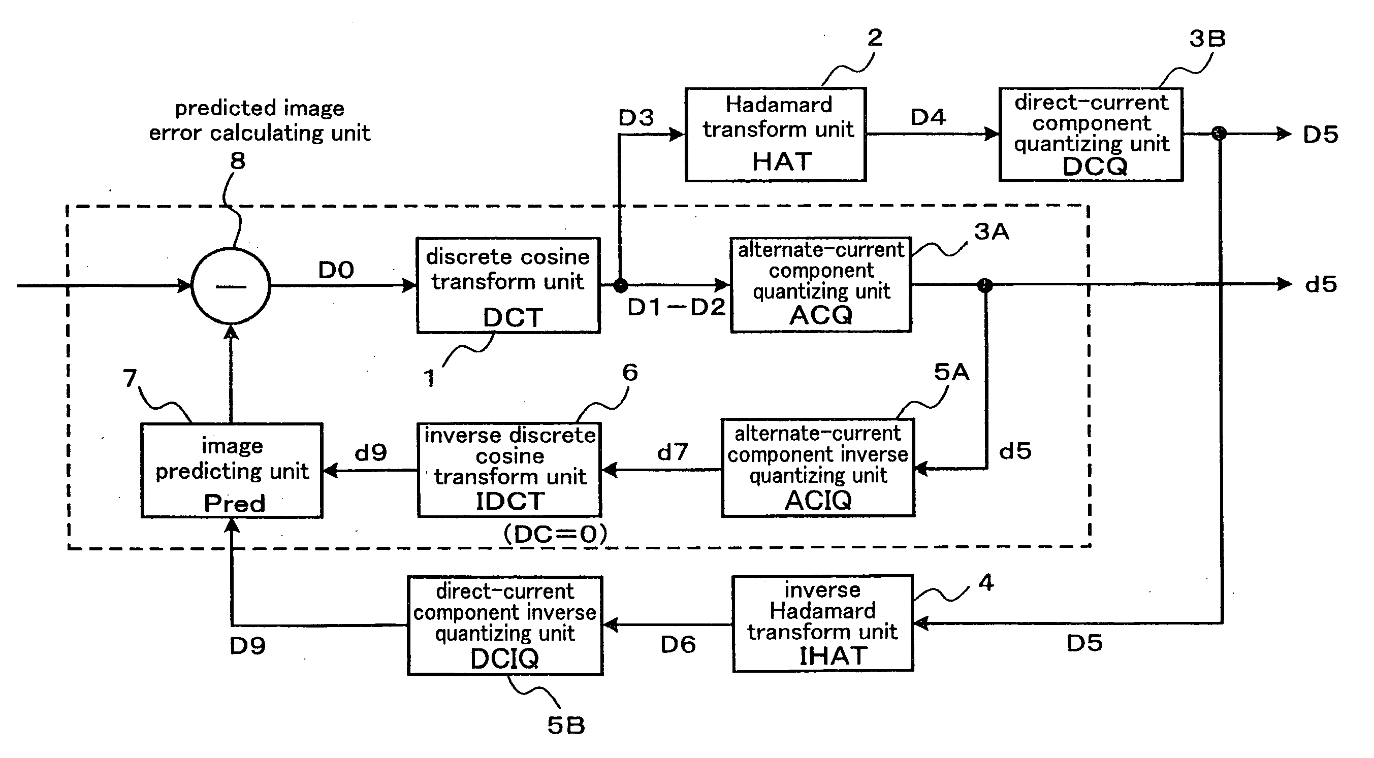
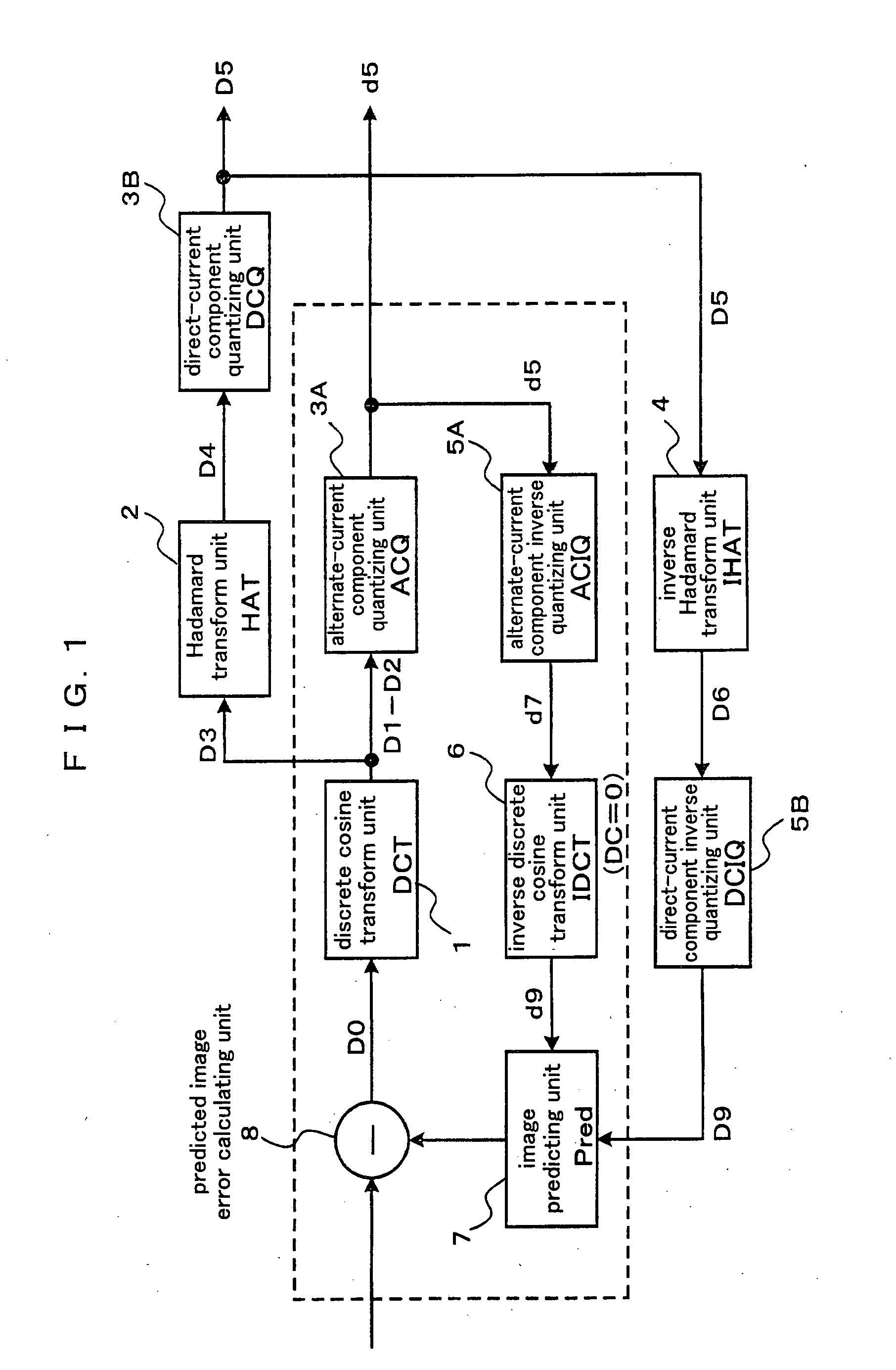
[0085]FIG. 1 is a block diagram illustrating a constitution of a signal processor (data compressing device) according to a preferred embodiment 1 of the present invention. The signal processor according to the present preferred embodiment comprises a discrete cosine transform unit 1, an Hadamard transform unit 2, an alternate-current component quantizing unit 3A, a direct-current component quantizing unit 3B, an inverse Hadamard transform unit 4, an alternate-current component inverse quantizing unit 5A, a direct-current component inverse quantizing unit 5B, an inverse discrete cosine transform unit 6, an image predicting unit 7, and a predicted image error calculating unit 8.
[0086]A subsequent stage of the discrete cosine transform unit 1 is divided into an alternate-current processing system and a direct-current processing system. The alternate-current processing system comprises the chronological components, which are the alternate-current component quantizi...
embodiment 2
PREFERRED EMBODIMENT 2
[0129]It is unnecessary to limit the orthogonal transform with respect to the direct-current component to the Hadamard transform. In a preferred embodiment 2 of the present invention, one of the Hadamard transform and the discrete cosine transform is selected as the orthogonal transform with respect to the direct-current component.
[0130]FIG. 6 is a block diagram illustrating a constitution of a signal processor (data compressing device) according to the preferred embodiment 2. In FIG. 6, the same reference symbols as those shown in FIG. 1 according to the preferred embodiment 1 show the same components. The constitution according to the present preferred embodiment is characterized in that an Hadamard transform unit 9A and a discrete cosine transform unit 9B are connected in parallel in the subsequent stage of the discrete cosine transform unit 1, and outputs of these components are selected in a selector 10 and supplied to the direct-current component quantizi...
embodiment 3
Preferred Embodiment 3
[0137]In the preferred embodiments 1 and 2, the present invention is applied to the constitution wherein an orthogonal transform is executed after another orthogonal transform is executed. However, the present invention is not limited thereto, and the present invention can be applied to a signal processor wherein the parameter of the direct-current component showing the processing result of the discrete cosine transform unit 1 is adjusted by a DC parameter adjusting unit 13 as shown in a preferred embodiment 3 of the present invention shown in FIG. 8. In the constitution shown in FIG. 8, the Hadamard transform unit 2 and the inverse Hadamard transform unit 4 are omitted, and the DC parameter adjusting unit 13 is provided.
[0138]Describing the parameter adjustment referring to an example shown in FIG. 9A, an increase / decrease coefficient for including a plurality of direct-current components D10 within such a level that is defined by an upper-limit value Th1 and ...
PUM
 Abstract
Description
Claims
Application Information