Distributed ultrahigh-speed disturbance quantitative detection method and device

A quantitative detection method and ultra-high-speed technology, which are applied to measurement devices, use optical devices to transmit sensing components, and convert sensor outputs. Strain value and other issues to achieve the effect of increasing the repetition frequency

Active Publication Date: 2016-12-21
NANJING UNIV
View PDF5 Cites 40 Cited by
  • Summary
  • Abstract
  • Description
  • Claims
  • Application Information

AI Technical Summary

Problems solved by technology

[0005] Although Φ-OTDR has many advantages, the currently commonly used Φ-OTDR also has obvious defects. Most of them can only detect the location of the strain and extract its frequency domain information, and cannot quantitatively measure the strain value.
The main reason is that there is no definite, one-to-one correspondence between the optical signal obtained by the receiving end and the strain value loaded on the fiber, so the strain value loaded on the fiber cannot be calculated by the demodulation algorithm
AMasoudi and M Belal of the University of Southampton in the UK used it in "A distributed optical fiber dynamic strain sensor based on phase-OTDR" Phase demodulation with coupler and time-delay fiber can realize the detection of amplitude, but as the sensing distance increases, the speed of Φ-OTDR disturbance measurement will drop rapidly; Zhang Yixin and Guo Zheng from the Optical Communication Engineering Research Center of Nanjing University In "Enhanced Ф-OTDR System for Quantitative Strain MeasurementBased on Ultra-Weak Fiber Bragg Grating Array", Bragg grating reflection signal is used for phase demodulation, but the frequency sweep control of laser is required, and the phase solution algorithm is relatively complicated. Φ-OTDR The measurement speed is therefore severely limited

Method used


Image

  • Distributed ultrahigh-speed disturbance quantitative detection method and device
  • Distributed ultrahigh-speed disturbance quantitative detection method and device
  • Distributed ultrahigh-speed disturbance quantitative detection method and device

Examples


Embodiment Construction

[0040] Below in conjunction with accompanying drawing, technical scheme of the present invention is described in further detail:

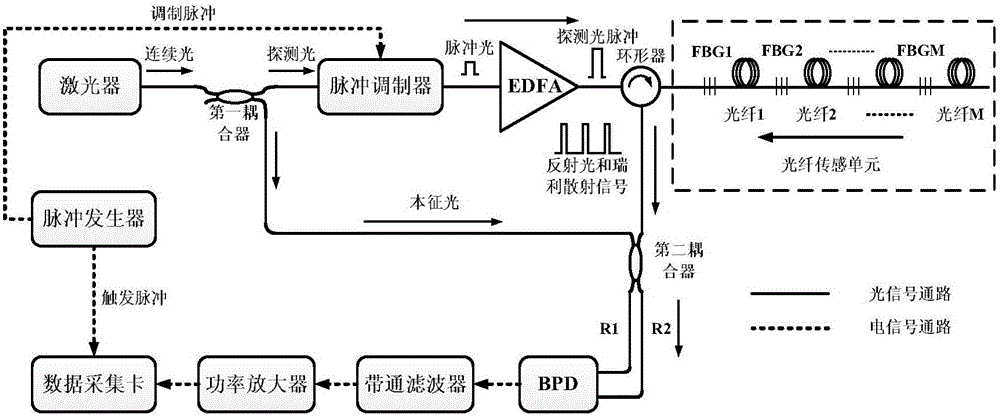
[0041] Such as figure 1 Shown is a device structure diagram of the present invention, a device based on a distributed ultra-high-speed disturbance quantitative detection method of the present invention, including a pulse generator, a laser, a first coupler, a pulse modulator, an erbium-doped fiber amplifier, a circulator, An optical fiber sensing unit, a second coupler, a balanced detector, a bandpass filter, a power amplifier and a data acquisition card; wherein,

[0042] The pulse generator is used to generate modulation pulses and trigger pulses; the modulation pulses are output to the pulse modulator, and the trigger pulses are output to the data acquisition card;

[0043] a laser, used to generate a continuous mode narrow linewidth laser, and output it to the first coupler;

[0044] The first coupler is used to divide the continuous mode nar...


PUM

PropertyMeasurementUnit
Reflectivityaaaaaaaaaa

Abstract

The invention discloses a distributed ultrahigh-speed disturbance quantitative detection method. Ultrahigh-speed disturbance detection can be realized through a time division multiplexing method; and phase demodulation is carried out through phase demodulation methods such as Hilbert transformation and orthogonal transformation so as to be able to realize real-time detection on the disturbance position, frequency and amplitude. The invention further discloses a distributed ultrahigh-speed disturbance quantitative detection device, which comprises a pulse generator, a laser, a first coupler, a pulse modulator, an erbium-doped optical fiber amplifier, a circulator, an optical fiber sensing unit, a second coupler, a balance detector, a band-pass filter, a power amplifier and a data acquisition card. According to the invention, the repetition frequency of detecting light pulses is improved through a time division multiplexing technology, so that a reflecting grating based phi-OTDR system is enabled to realize ultrahigh-speed disturbance detection; and real-time detection for the disturbance position, frequency and amplitude is realized through the phase demodulation method by using a coherent detection structure and combining a phase unwrapping algorithm.

Description

technical field [0001] The invention relates to the technical field of optical fiber sensing, in particular to a distributed ultra-high-speed disturbance quantitative detection method and device. Background technique [0002] The phase-sensitive optical time domain reflectometer (Φ-OTDR) has the characteristics of high sensitivity, fast measurement speed, and simple structure. Protection and other fields have great application prospects, and the Φ-OTDR system has therefore become a hot spot in the research of sensing technology at home and abroad. [0003] Φ-OTDR uses the coherent fading effect of Rayleigh scattered light in the optical fiber for sensing, and can detect the location and frequency domain information of the disturbance event acting on the optical fiber. Compared with Optical Time Domain Reflectometer (OTDR), Φ-OTDR must use frequency stable narrow linewidth laser in order to obtain usable time domain curve of back Rayleigh scattered light. When a short pulse...

Claims


Application Information

Patent Timeline
IPC IPC(8): G01D5/353
CPCG01D5/35361
Inventor 张益昕乔苇岩张旭苹单媛媛孙振鉷王清曹露
Owner NANJING UNIV
Why Eureka
Try Eureka