
Control system and method for estimating turbocharger performance

a technology of control system and performance estimation, which is applied in the direction of electric control, machines/engines, mechanical equipment, etc., can solve the problems of unreliable estimation, unreliable estimation, and high system cost, and achieve the effect of reducing the cost of system maintenance and repair, and reducing the cost of maintenance and repair

Active Publication Date: 2007-11-20
CATERPILLAR INC
View PDF23 Cites 42 Cited by
  • Summary
  • Abstract
  • Description
  • Claims
  • Application Information

AI Technical Summary

Benefits of technology

The present patent is about a control system and method for estimating the performance of a compressor. The system includes sensors to measure the speed, pressure, temperature, and atmospheric pressure of the compressor. By monitoring these indicators, the control system can estimate the inlet pressure of the compressor. This information can be used to optimize the performance of the compressor and improve the overall performance of the power source.

Problems solved by technology

Although the system of the '457 patent may provide ways to sufficiently estimate the pressure ratio, efficiency, and outlet temperature of a compressor, it may be expensive and unreliable.
In particular, because of the number of sensory inputs, the cost of system may be substantial.
In addition, because the outputs of the system rely on the large number of sensory inputs, a failure of one of the sensory inputs could produce unreliable estimations.

Method used


Image

  • Control system and method for estimating turbocharger performance
  • Control system and method for estimating turbocharger performance
  • Control system and method for estimating turbocharger performance

Examples


Embodiment Construction

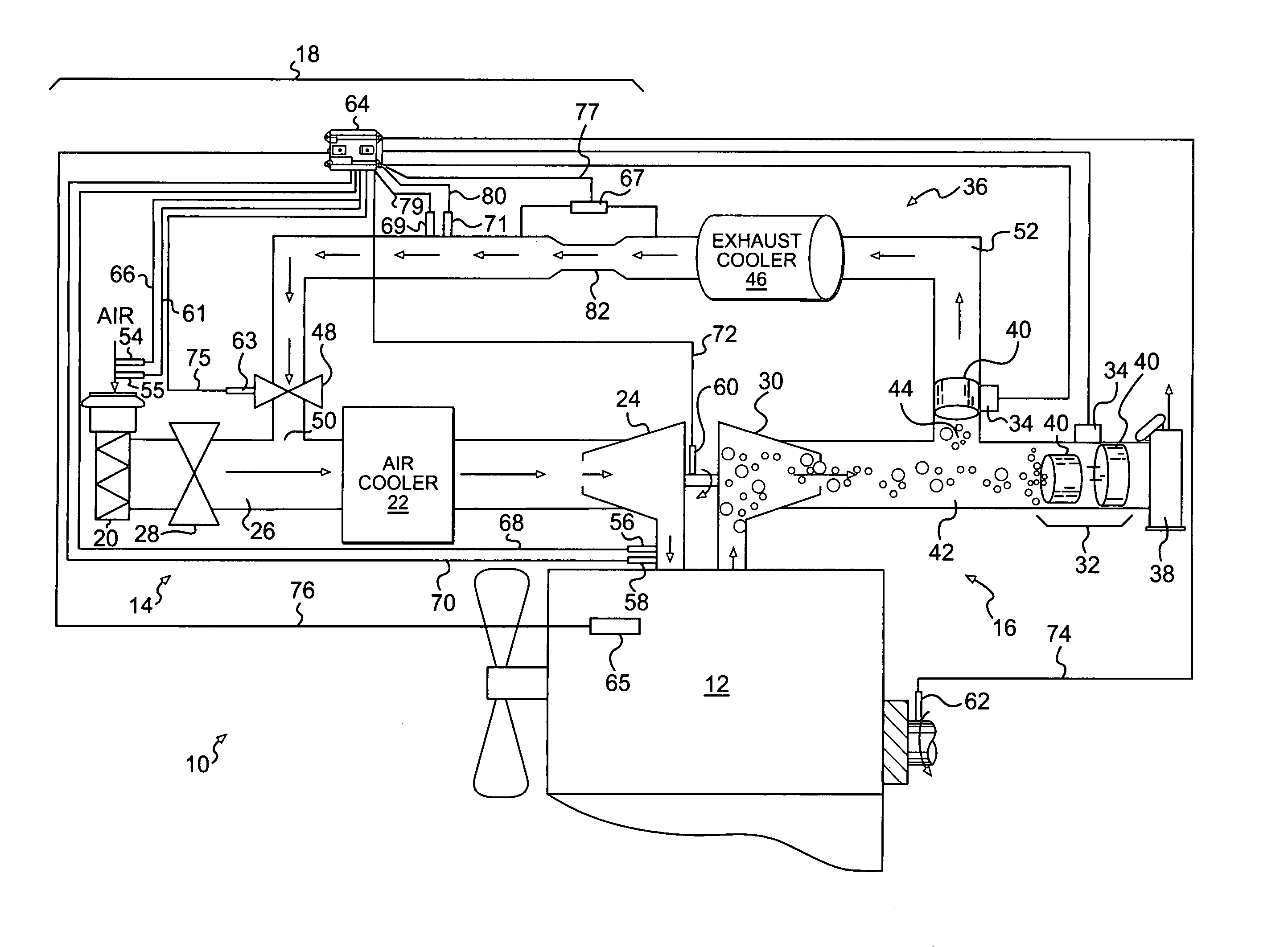
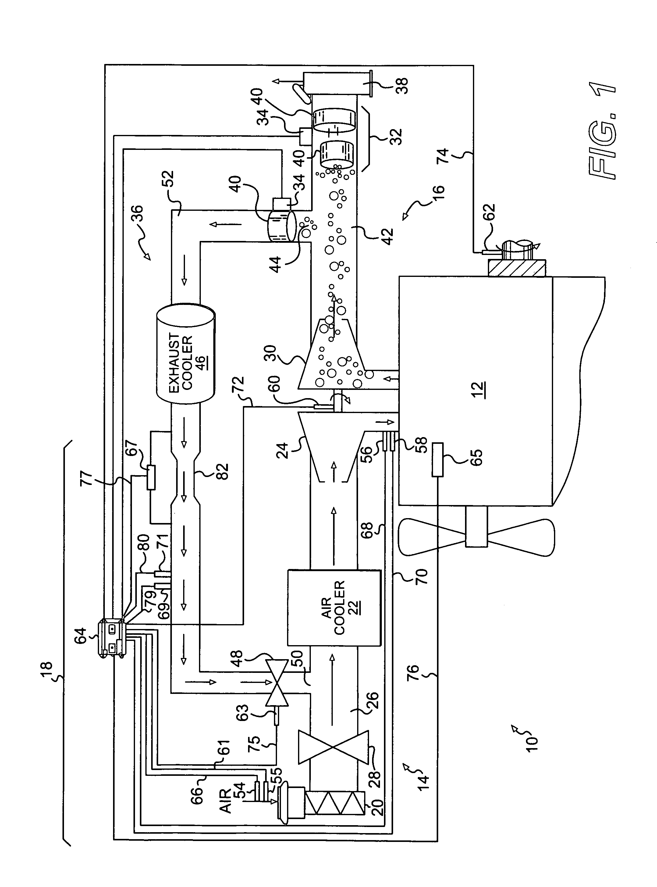
[0012]FIG. 1 illustrates an exemplary machine 10 having multiple systems and components that cooperate to accomplish a task. Machine 10 may perform some type of operation associated with an industry such as mining, construction, farming, transportation, power generation, or any other industry known in the art. For example, machine 10 may embody a mobile machine such as an on-highway vocational vehicle, an off-highway haul truck, an excavator, a dozer, a loader, a motor grader, or any other load moving machine. Machine 10 may alternatively embody a stationary machine such as a generator set, a furnace, or another suitable stationary machine. Machine 10 may include a power source 12, an air induction system 14, an exhaust treatment system 16, and a control system 18.

[0013]Power source 12 may include a combustion engine having multiple subsystems that interact to produce mechanical and / or electrical power output and a flow of exhaust gas. For the purposes of this disclosure, power sour...


PUM


Abstract

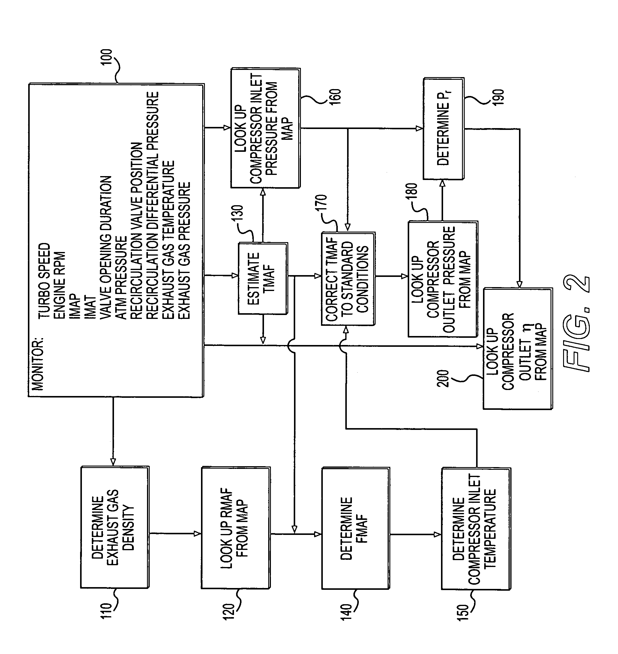
A control system for estimating the performance of a compressor is disclosed. The control system has a compressor fluidly connected to an inlet manifold of a power source. The control system also has a power source speed sensor to provide an indication of a rotational speed of the power source, an inlet pressure sensor to provide an indication of a pressure of a fluid within the inlet manifold, an inlet temperature sensor to provide an indication of a temperature of the fluid within the inlet manifold, an atmospheric pressure sensor to provide an indication of an atmospheric pressure, and a control module in communication with each of the sensors. The control module is configured to monitor an engine valve opening duration and an exhaust gas recirculation valve position, and estimate a compressor inlet pressure based on the provided indications, the monitored duration, and the monitored position.

Description

TECHNICAL FIELD[0001]The present disclosure is directed to a turbocharger control system and, more particularly, to a control system and method for estimating the performance of a turbocharger.BACKGROUND[0002]Internal combustion engines such as, for example, diesel engines, gasoline engines, and gaseous fuel powered engines are supplied with a mixture of air and fuel for subsequent combustion within the engine that generates a mechanical power output. In order to maximize the power generated by this combustion process and reduce levels of resultant pollutants, the engine is often equipped with a turbocharged air induction system that implements exhaust gas recirculation (EGR).[0003]A turbocharged air induction system includes a turbocharger that uses exhaust from the engine to compress air flowing into the engine, thereby forcing more air into a combustion chamber of the engine than the engine could otherwise draw into the combustion chamber. This increased supply of air allows for ...

Claims


Application Information

Patent Timeline
Patent Type & Authority Patents(United States)
IPC IPC(8): F02B33/00
CPCF01N11/002F02B39/16F02D41/0007F02D41/0072F02M25/0754Y02T10/47F02D2041/001F02D2200/0406F02D2200/0408F02D2200/0414F02D2200/703F02M25/0709F02M25/0727F02M25/074F02M25/0742Y02T10/144F02B29/0406F02M26/06F02M26/23F02M26/35F02M26/36F02M26/47Y02T10/12Y02T10/40
Inventor WITHROW, MICHAEL P.DEA, KEVIN L.GEHRKE, CHRISTOPHER R.DONOHO, II, MICHAEL R.
Owner CATERPILLAR INC
Learn More